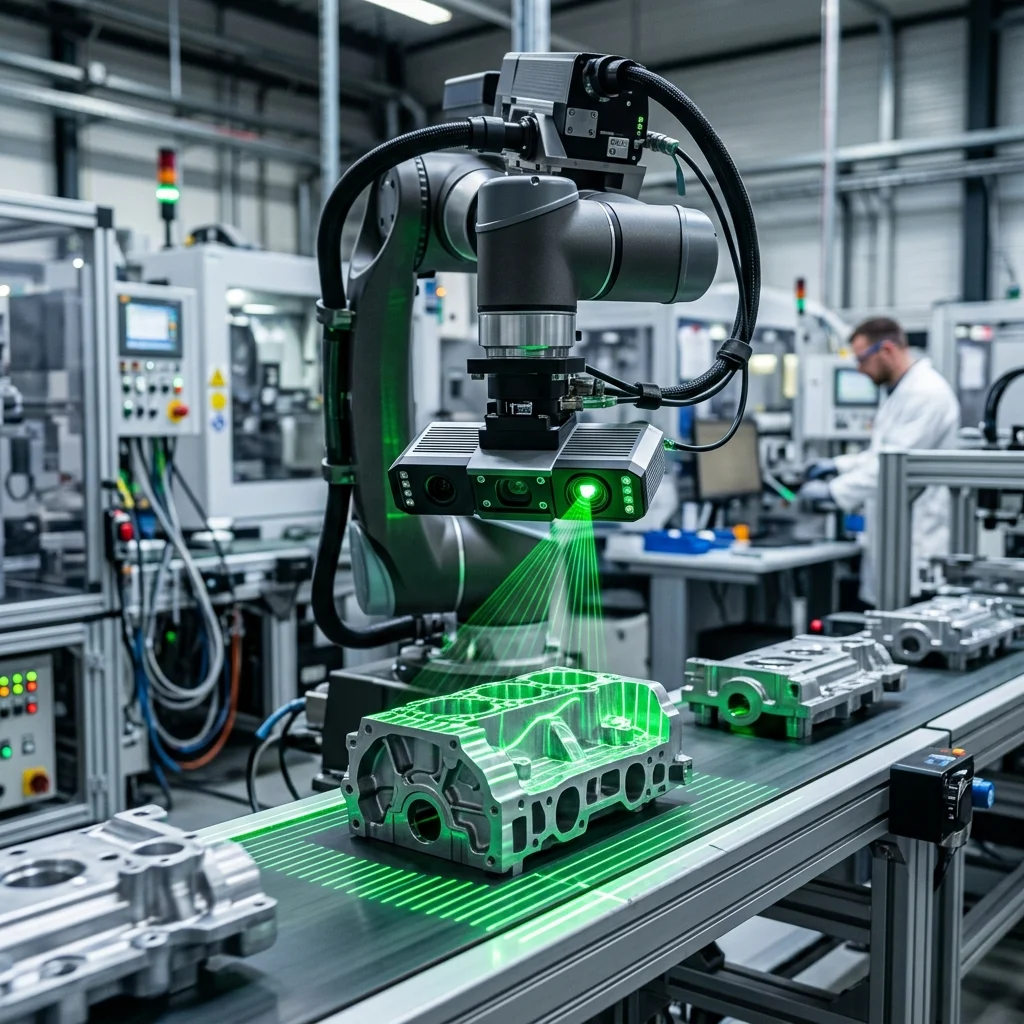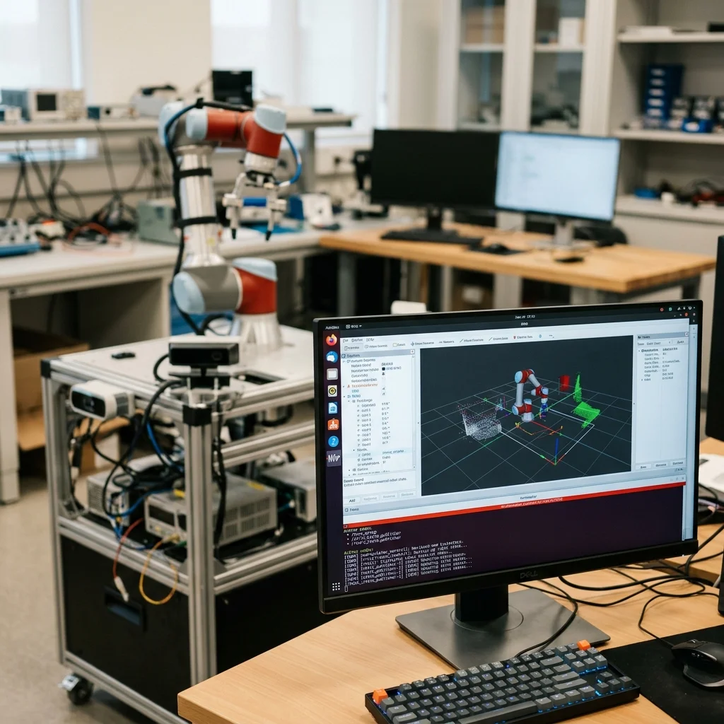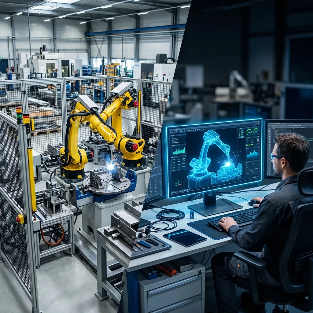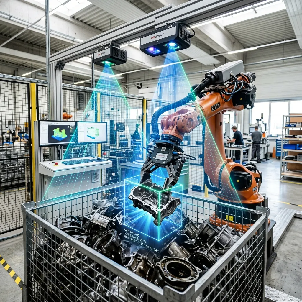
3D vision-guided bin picking allows industrial robots to locate, select, and pick randomly oriented parts directly from deep bins without the need for expensive mechanical feeders or custom fixtures. Implementing this technology requires matching a high-resolution structured light or time-of-flight 3D camera with advanced collision-free path planning software and flexible gripper configurations capable of reaching deep into container corners.
Understanding 3D Camera Technologies
Traditional 2D cameras are limited to flat, high-contrast surfaces, making them unsuitable for picking overlapping or dirty parts from deep boxes. 3D vision systems overcome this by measuring depth. The most common technology for industrial bin picking is structured light, where a projector casts a known pattern onto the bin and a camera measures the distortion of the pattern to calculate a dense 3D point cloud.
Another option is Time-of-Flight (ToF) cameras, which measure the time it takes for a light pulse to bounce back from the object. ToF systems are faster but generally offer lower resolution than structured light systems. Selecting the correct camera technology requires balancing required accuracy, part size, ambient lighting conditions, and the reflectivity of the material being scanned.
Calibration: Hand-Eye and Tool Center Point (TCP)
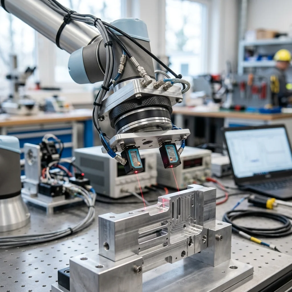
Positional accuracy in vision-guided cells depends entirely on camera-to-robot calibration. In a hand-eye configuration, the camera is mounted directly on the robot's arm, meaning the camera moves with the tool. This setup offers high accuracy but increases cycle times as the robot must pause to take a scan. Alternatively, fixed-camera systems mount the scanner above the bin, allowing simultaneous scanning and movement.
Both methods require a calibration routine where the robot touches a target block at various angles, mapping the camera's pixels to the robot's physical coordinates. Any error in this mapping, or in the definition of the Tool Centre Point (TCP), will result in misplaced grips and collisions, highlighting the need for rigid mounts that resist thermal expansion and floor vibrations.
Path Planning and Collision Avoidance
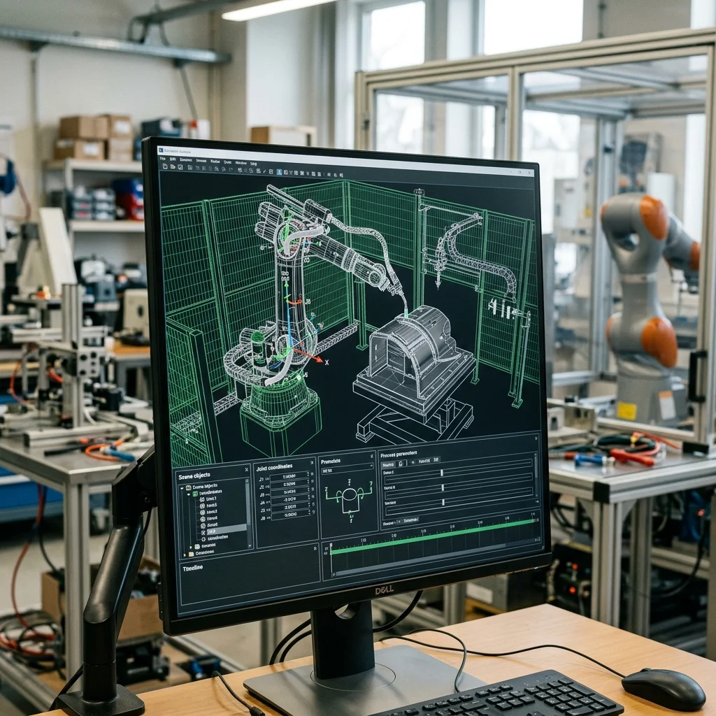
Locating the part is only half the battle; the robot must also find a safe path to reach it. Deep bins present significant collision hazards, as the robot's arm or end-of-arm tool (EOAT) can easily strike the bin walls. Path planning software uses the 3D point cloud of the bin and parts, combined with a CAD model of the robot and gripper, to calculate a collision-free approach vector.
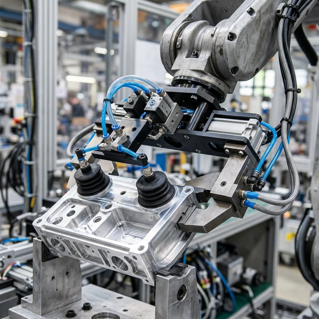
The software must model not only the empty gripper but also the gripper holding the part, as the combined profile changes during extraction. Integrators should design long, slender grippers with active collision sensors, allowing the robot to tilt its wrist to reach corners without hitting structural frames, ensuring high pick rates even as the bin empties.