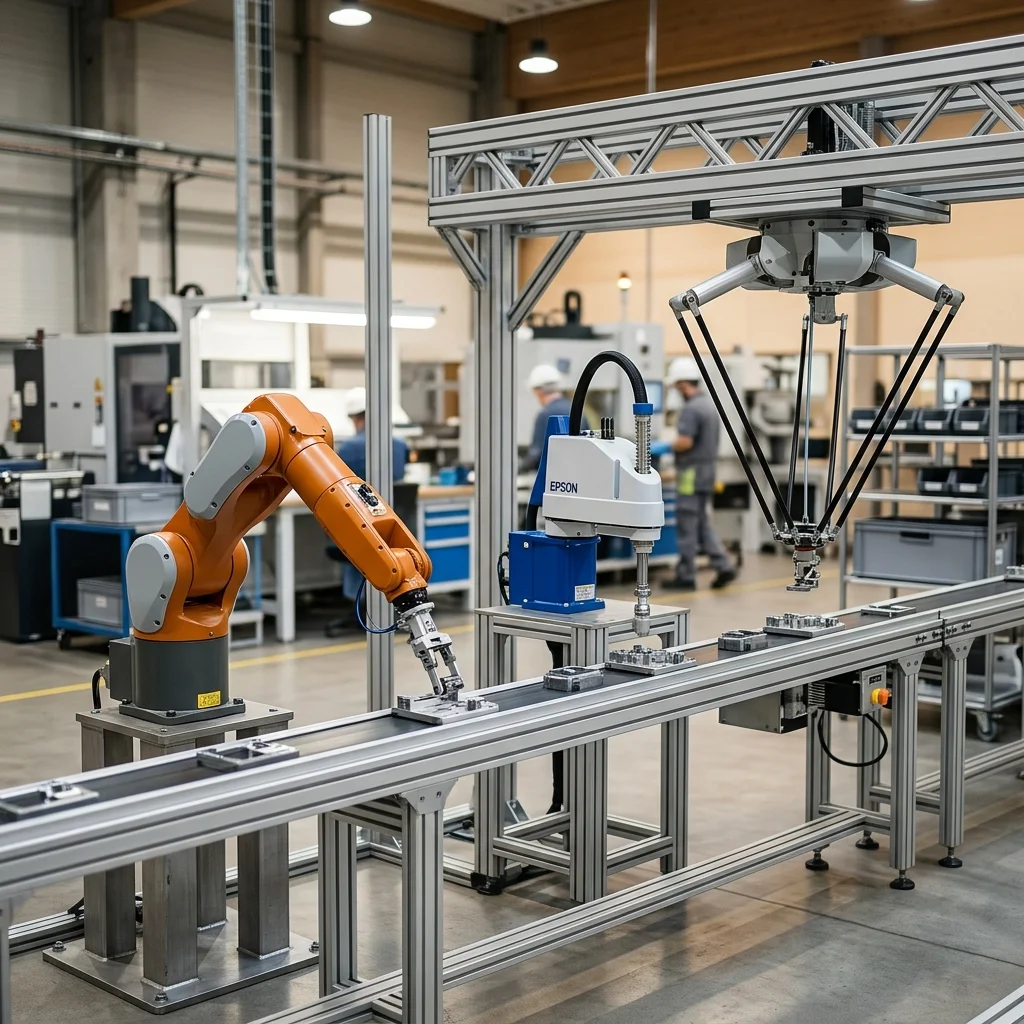
Selecting the correct industrial robot depends on balancing three critical parameters: payload capacity, reach/working envelope, and required cycle times. Articulated robots offer maximum flexibility for complex, multi-axis paths; SCARA robots excel at high-speed vertical assembly tasks with planar movement; and Delta robots are the optimal choice for high-speed, low-payload pick-and-place operations.
Introduction to Robotic Kinematics and Topology
Kinematic configurations define the mechanical boundaries of what an automated system can achieve on the factory floor. Before investing in a robotic arm, controls engineers must analyse the robot's joint structure and how it relates to the task at hand. The three most common configurations on modern assembly lines are articulated (6-axis), SCARA (Selective Compliance Assembly Robot Arm), and Delta (parallel link) robots. Each of these topologies has been developed to optimise specific kinematic behaviours and path characteristics.
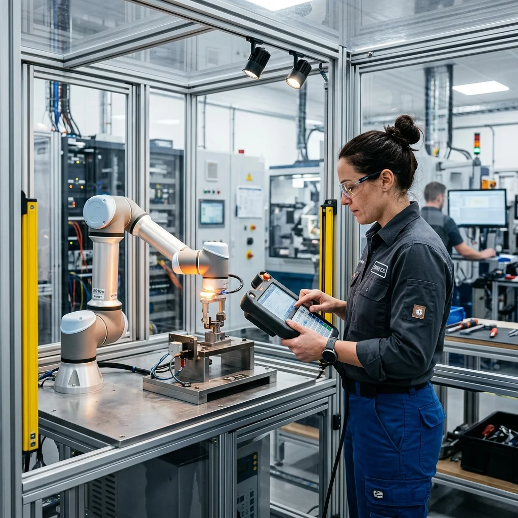
Articulated robots simulate human arm movements, offering six degrees of freedom. This allows them to reach around obstacles and orient tools at almost any angle. SCARA robots, by contrast, rely on a rigid vertical axis paired with two rotational joints in the horizontal plane, creating a cylindrical work envelope. Delta robots use a system of parallelograms connected to a single base, keeping the end-effector platform parallel to the ceiling. Understanding these physical constraints is the first step toward avoiding costly deployment errors.
When selecting a kinematic structure, one must favour operational requirements over marketing promises. For instance, a six-axis arm is often over-specified for basic pick-and-place routines, leading to unnecessary mechanical wear and higher energy draw. Conversely, forcing a SCARA robot to perform tasks requiring 3D path rotation, such as complex deburring, will result in poor tolerances and premature component failure. Aligning the physical mechanics of the arm to the geometric requirements of the component is essential for long-term cell reliability.
Kinematic Envelopes, Reach, and Joint Limits
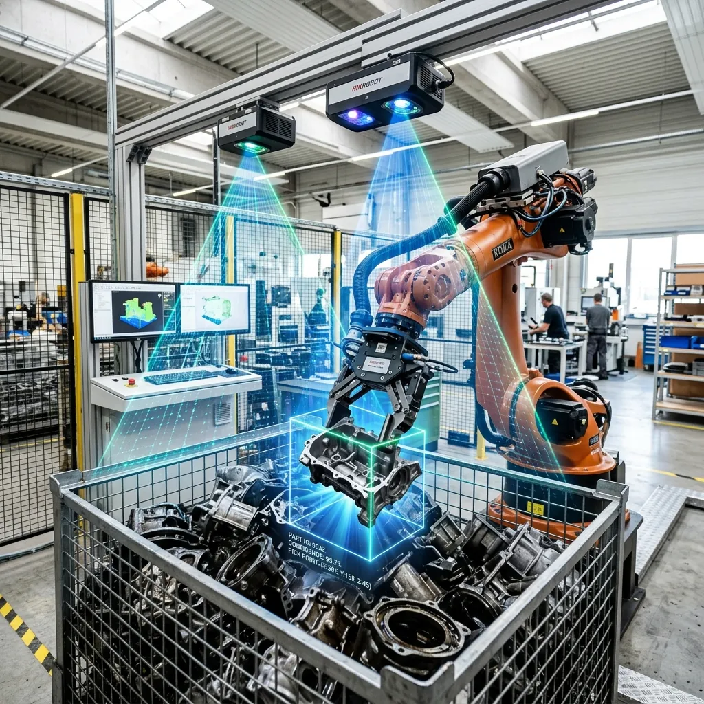
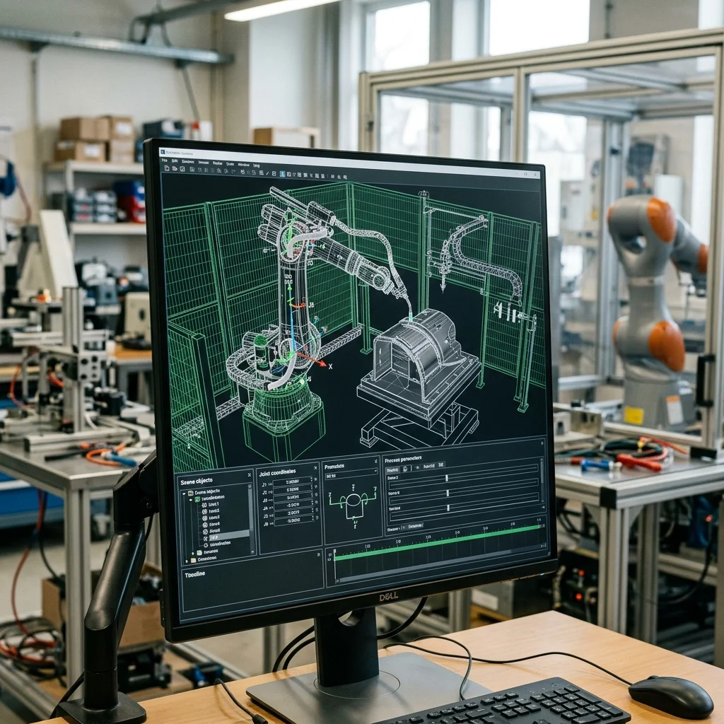
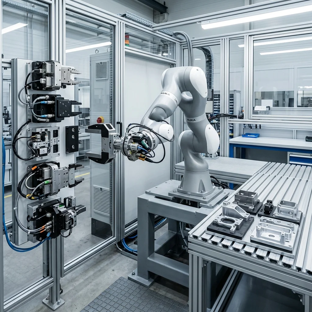
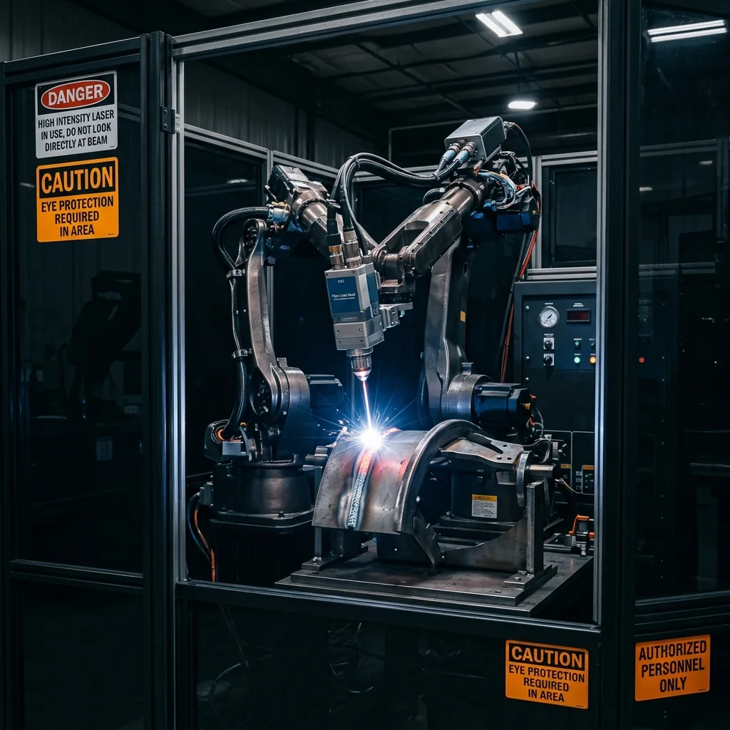
When planning a cell layout, reach simulation is critical to verify that the robot can access all pickup and deposit points without violating joint limits or entering singularity states. An articulated robot provides the largest spherical workspace. This makes it suitable for welding, dispensing, and machine tending where the robot must work in three dimensions. In 3D space, reach simulations using digital twins are essential to ensure the arm does not collide with tooling fixtures or the workpiece itself.
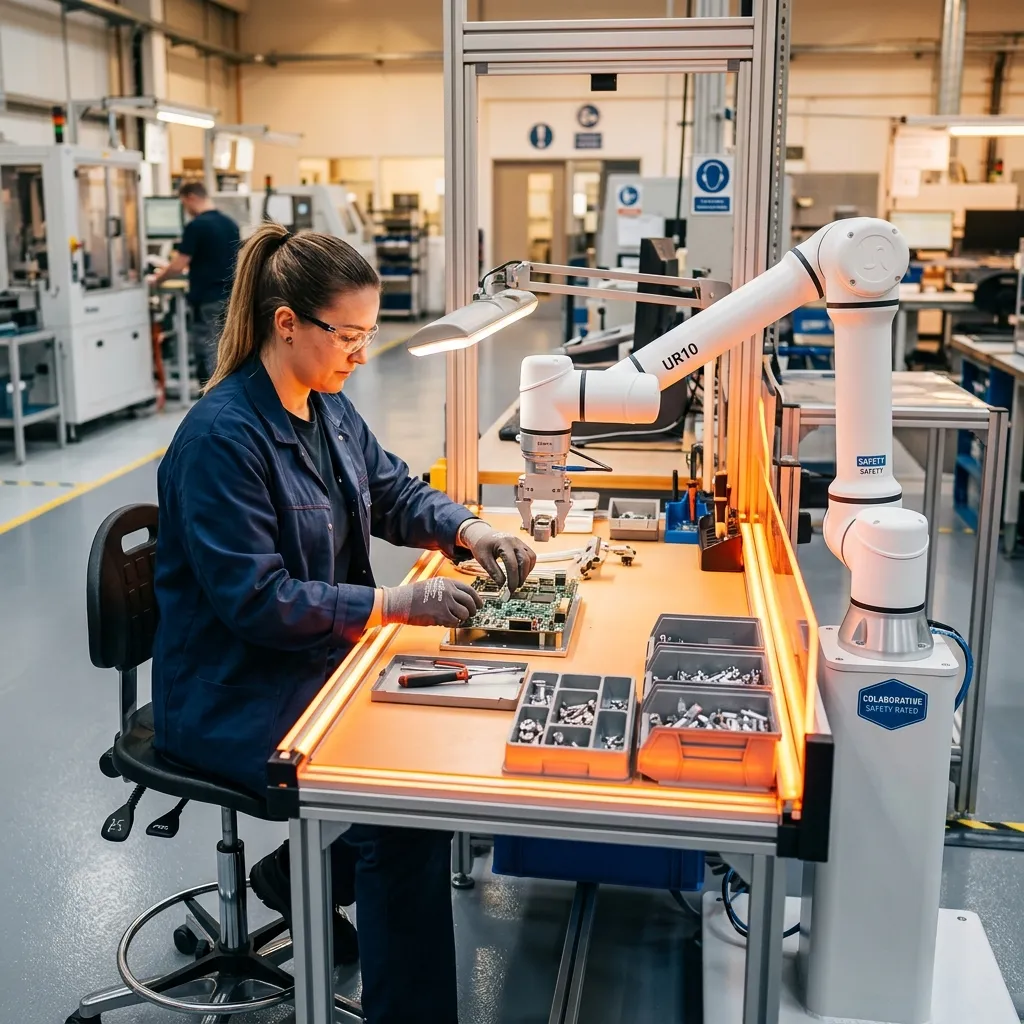
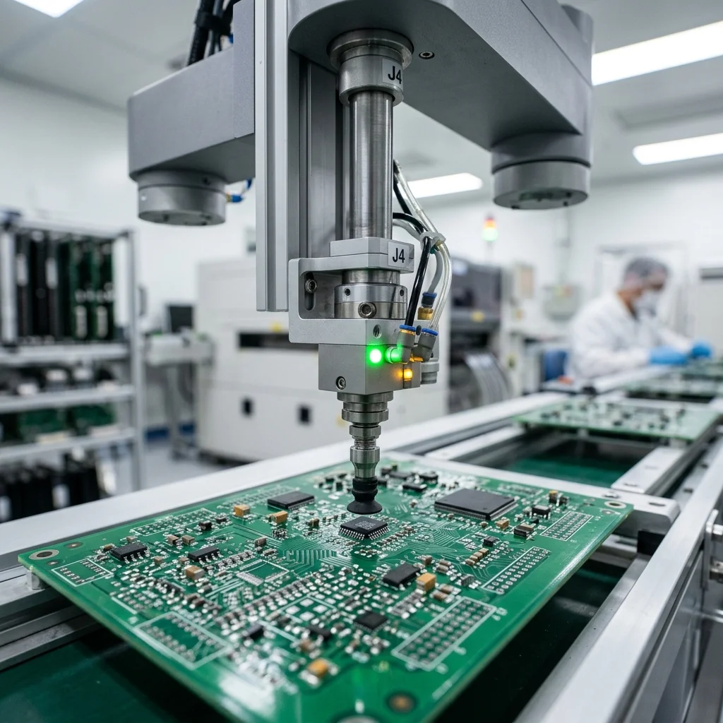
A key concept in articulated robotics is the singularity state, where two or more axes align collinearly, causing the robot control system to demand infinite velocity from a joint. In contrast, SCARA robots suffer less from these kinematic traps. A SCARA's workspace is cylindrical, limited by the length of the link arms and the stroke length of the vertical Z-shaft (quill). SCARAs are highly suited for tabletop assembly because their horizontal joints are compliant (flexible) while their vertical axis is rigid. This makes them ideal for inserting components into circuit boards or housings.
Delta robots operate within a dome-like workspace directly beneath their parallel arms. Their reach is relatively small compared to their physical footprint, but their speed within this workspace is unmatched. Because the heavy motors of a Delta robot are mounted statically on the overhead frame, the moving mass is minimised. This allows acceleration rates up to 10G or 15G. For any of these models, offline programming (OLP) tools should be used to simulate joint velocity profiles, ensuring that the robot does not exceed its torque limits during fast directional changeovers.
Cycle Times, Acceleration Profiles, and Payload Calculations
Cycle-time analysis must take into account not just the nominal speed of the robot, but also its acceleration capabilities and path deceleration. For high-speed applications, Delta robots are the standard, capable of exceeding 150 picks per minute. The lack of rotational joints on the moving arm keeps inertia low, allowing the delta mechanism to react instantly. This configuration is widely deployed in high-throughput food packaging and electronics sorting lines where fractions of a second determine the profitability of the line.
SCARA robots offer slightly lower acceleration but can still maintain cycle times under 0.4 seconds for standard pick-and-place cycles. The motors of a SCARA are located at the joints, meaning the robot must carry its own motor mass, limiting its acceleration compared to Delta models. However, SCARAs have a much higher payload capacity than Delta robots. While a typical Delta robot is limited to payloads below 10 kg, SCARA robots can comfortably handle up to 20 kg, making them suitable for heavier assembly tasks, such as battery pack assembly or heavy mechanical parts handling.
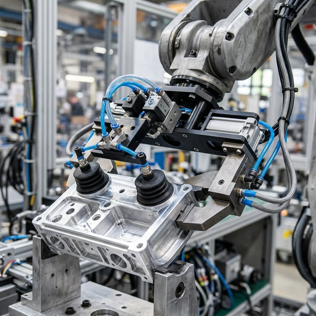
Articulated robots are the slowest of the three due to their high moving mass, but they handle far larger payloads. A typical 6-axis robot can support payloads from 3 kg up to several tonnes, whereas SCARA payloads are usually capped at 20 kg, and Deltas rarely exceed 10 kg. When calculating payload, engineers must include the weight of the gripper, sensors, cables, and the heaviest workpiece. Exceeding the payload limit leads to motor overheating, brake wear, and loss of path repeatability, which eventually halts production.
Part Tolerances and Path Repeatability
Path repeatability and positional accuracy are crucial when selecting a robot for precision tasks. SCARA robots generally offer the best repeatability in the horizontal plane (often within ±0.01 mm), making them the industry standard for electronics assembly and semi-conductor handling. The rigid mechanical linkages prevent horizontal drift under load, assuring that components are placed with extreme precision. This stiffness makes them highly robust against external forces encountered during pressing operations.
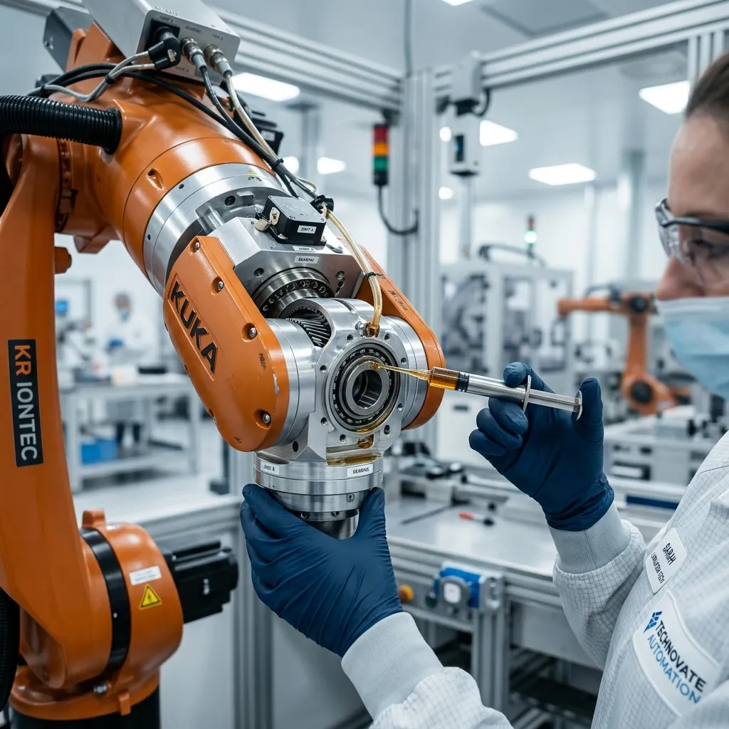
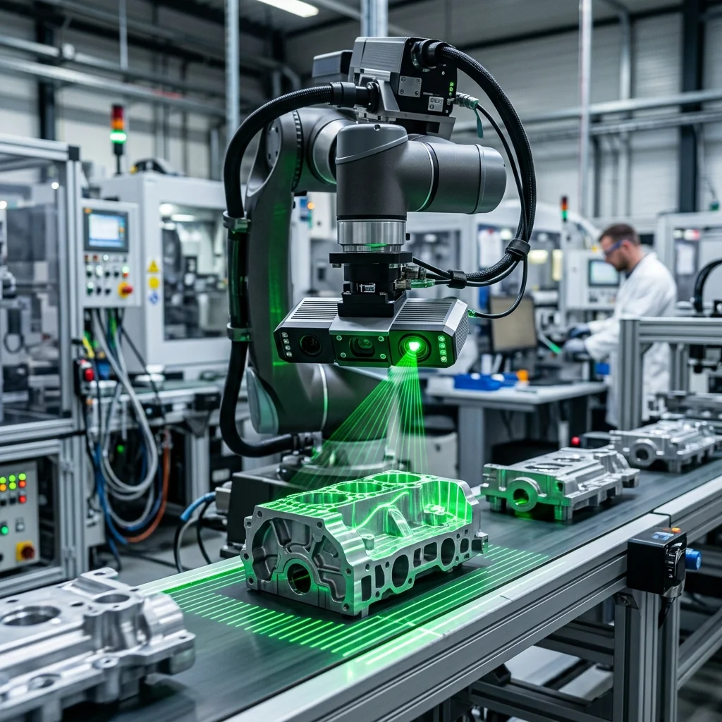
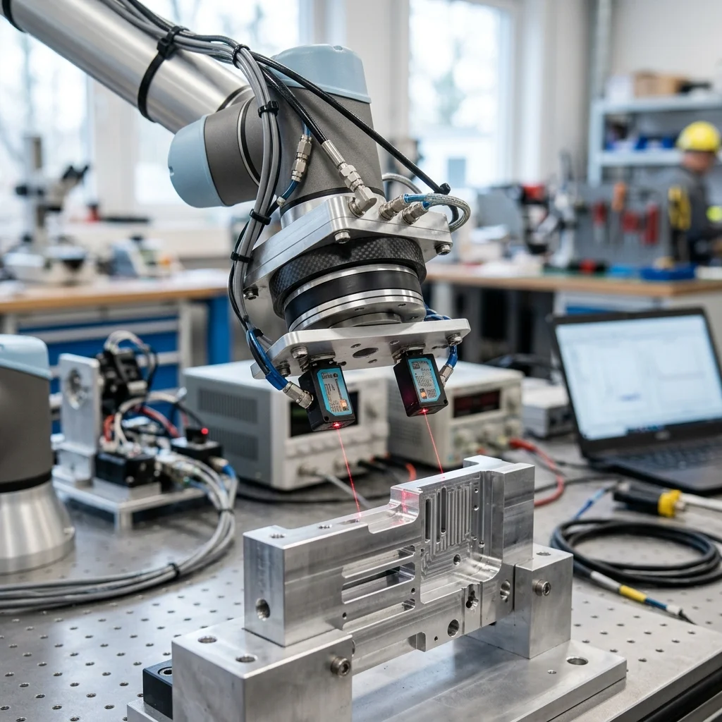
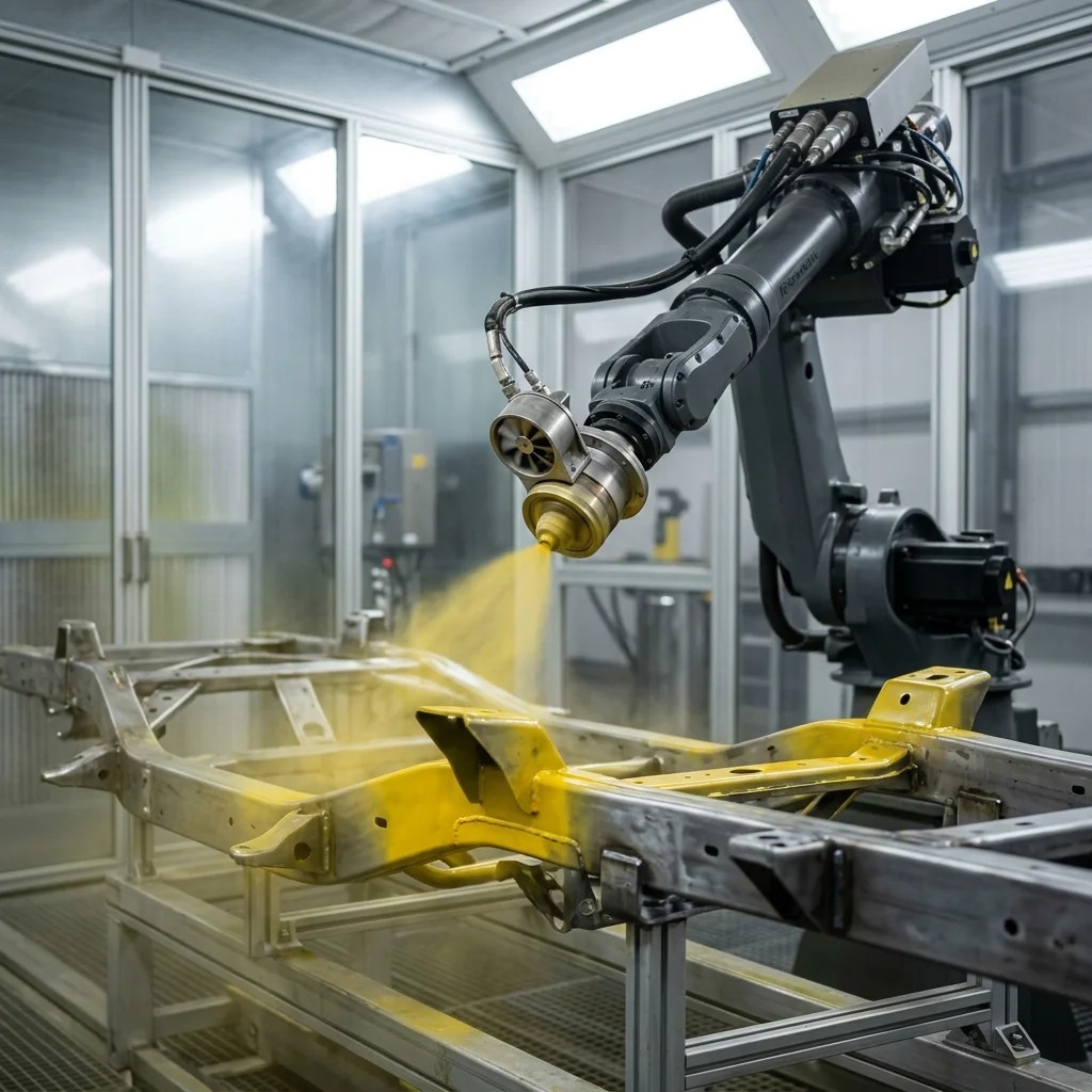
Articulated robots typically have a repeatability range between ±0.02 mm and ±0.1 mm, which is adequate for welding, painting, and packaging but less suitable for micro-assembly. Because they have more joints, tolerance stack-up and gearbox backlash are more pronounced. Over time, gear wear can introduce slight deviations in the path. Therefore, regular calibration cycles using laser trackers or optical measurement probes are recommended to maintain precision in high-tolerance applications.
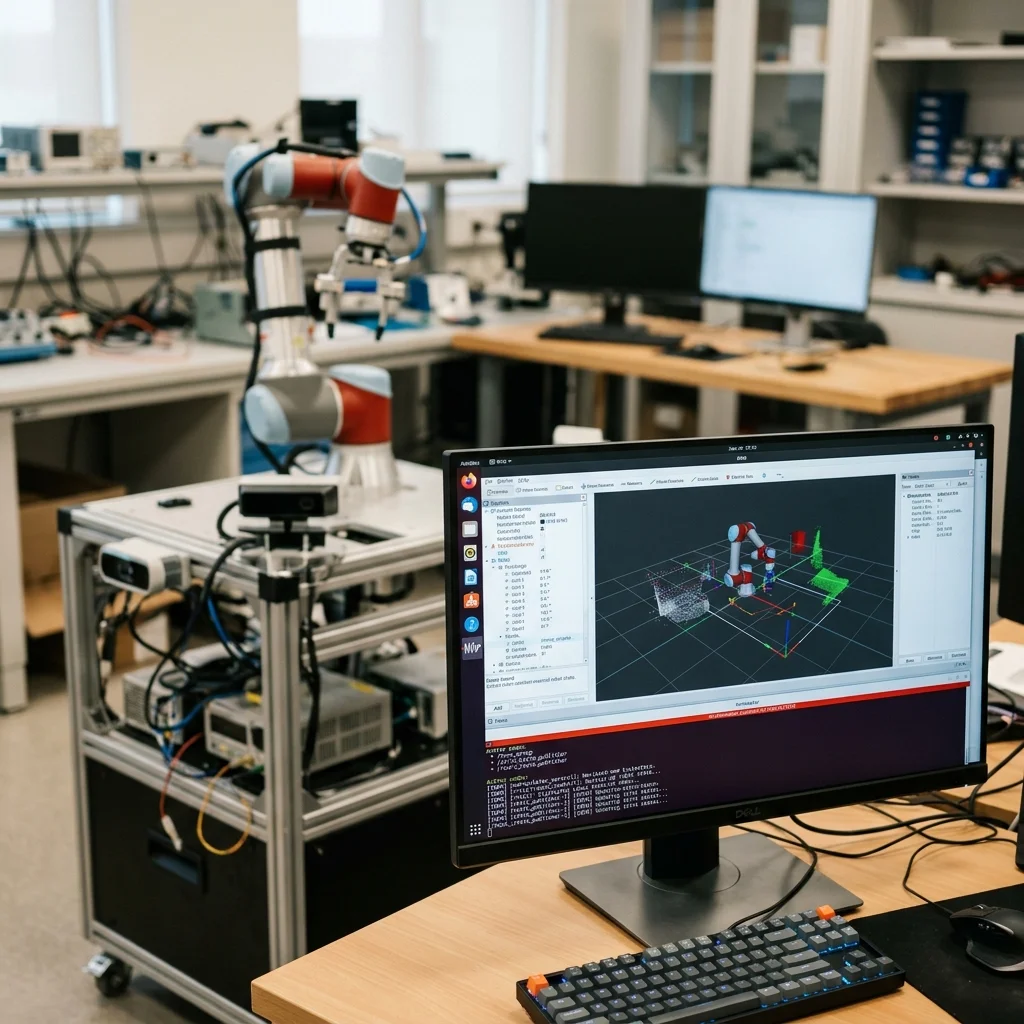
Delta robots exhibit repeatability of ±0.05 mm, which is excellent for food packaging and pharmaceutical sorting, but their parallel linkages can flex under heavy payloads, impacting absolute accuracy if the tools are unbalanced. When integrating machine vision, calibration between the camera coordinate system and the robot base coordinates is essential. Any misalignment here will negate the mechanical precision of the robot, leading to rejected parts or assembly failures.
Practical Floor Checklist for Deployment
Before finalising a robotic topology, manufacturing engineers should run through a checklist to ensure the cell meets the physical constraints of the production line. First, perform an envelope assessment using 3D simulation tools to ensure all pick-and-place coordinates are reachable without pushing joints close to 100% capacity. This prevents the robot from running into mechanical limits during operation.
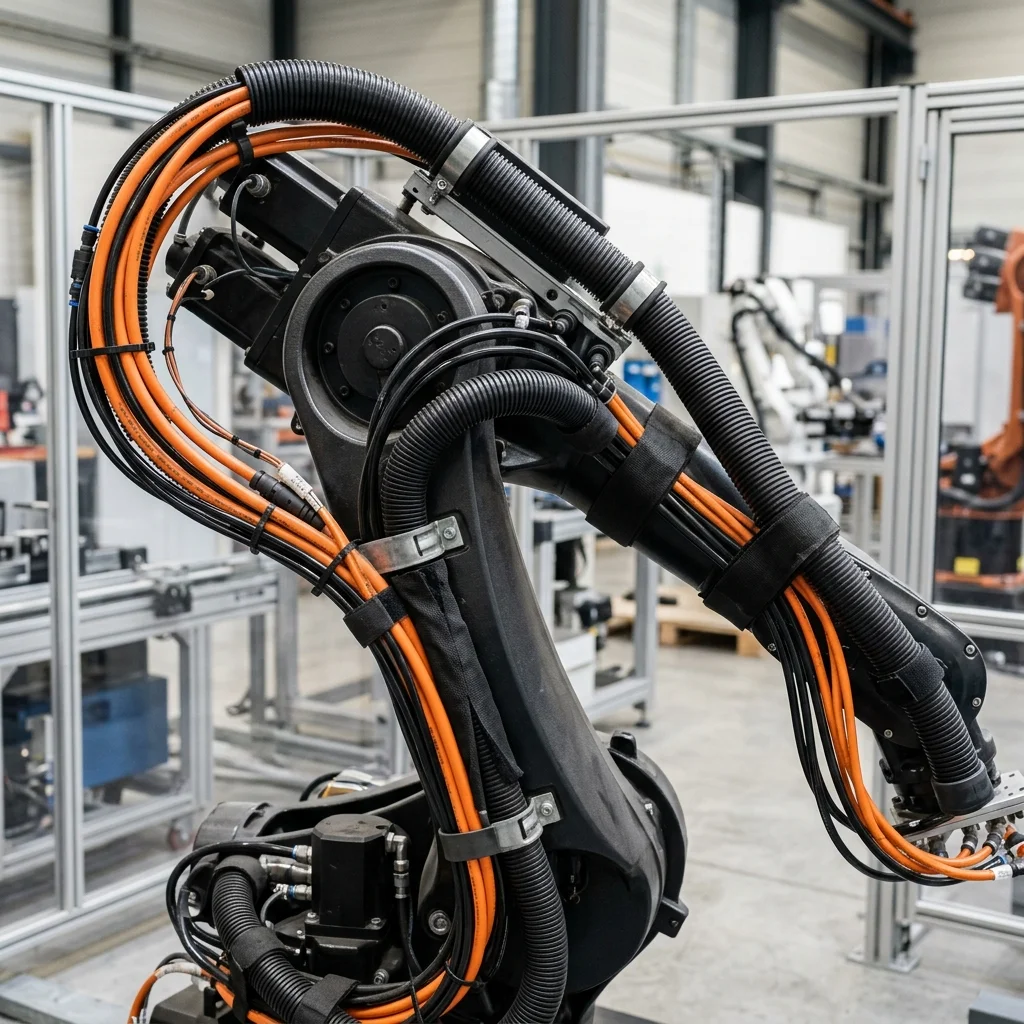
Second, ensure the mounting surface (floor, pedestal, or ceiling frame for Delta robots) is rigid enough to withstand the dynamic forces generated during peak acceleration. A flimsy pedestal will vibrate, causing path deviations and triggering collision alarms. Third, plan the routing of air lines, sensor cables, and power conduits to prevent cable wear and tear during rapid joint rotations. Cable management is a major source of downtime in robotics.
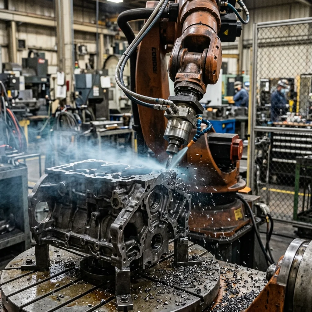
Finally, verify if the robot requires a specific IP rating (e.g., IP67 for washdown environments in food processing or dust protection in foundries). Standard robots will quickly fail if exposed to cutting fluids, grinding dust, or aggressive cleaning agents. Selecting the correct environmental package from the outset prevents premature failures and extends the operating life of the robot.