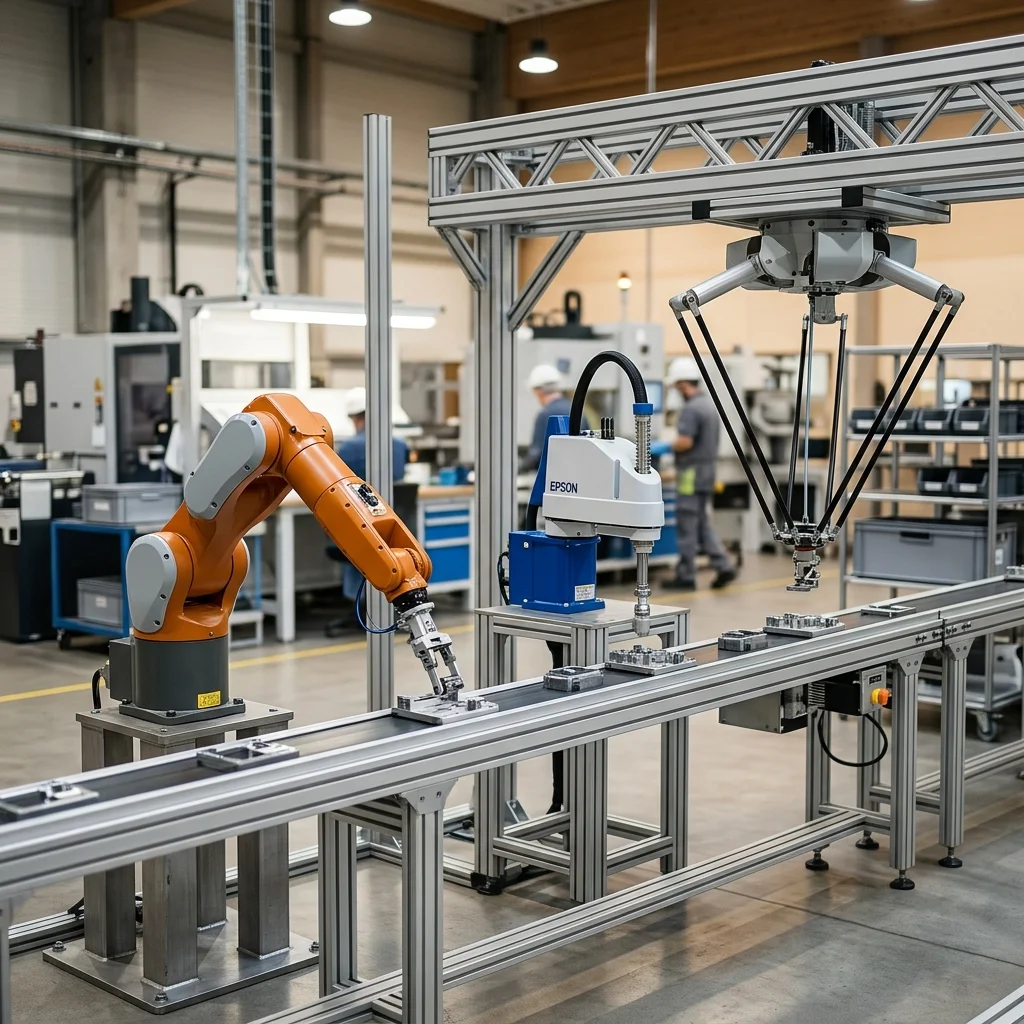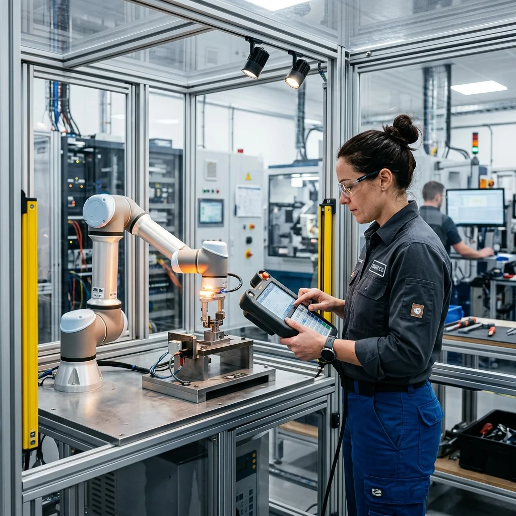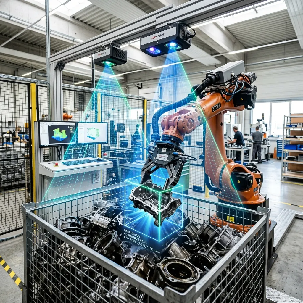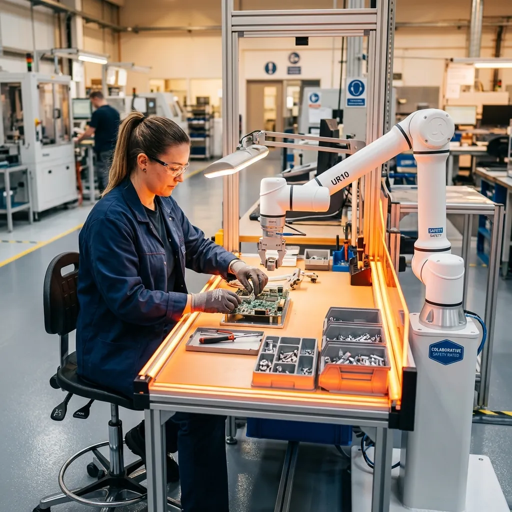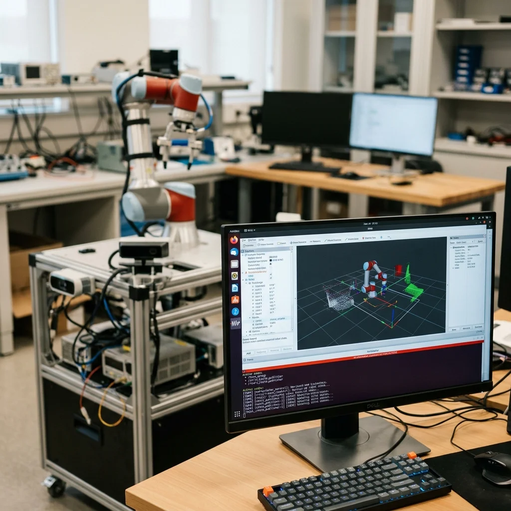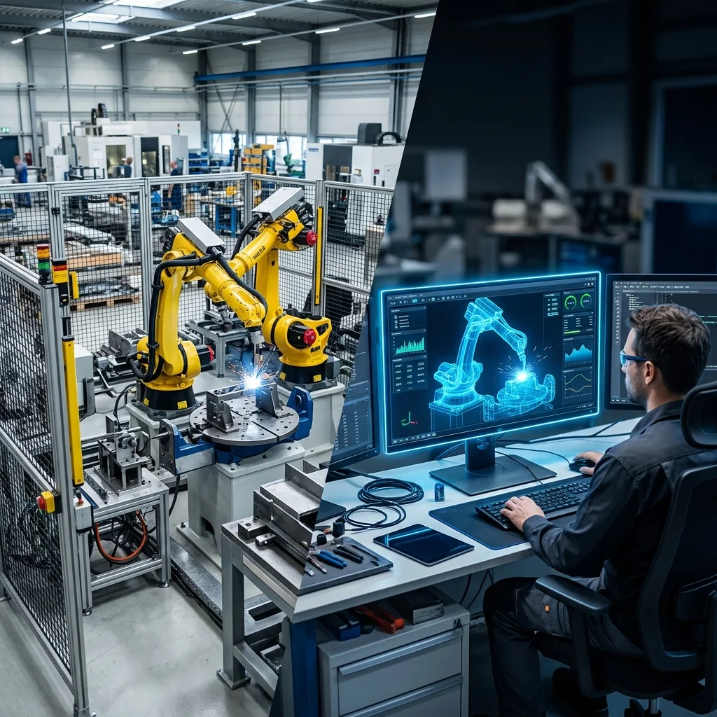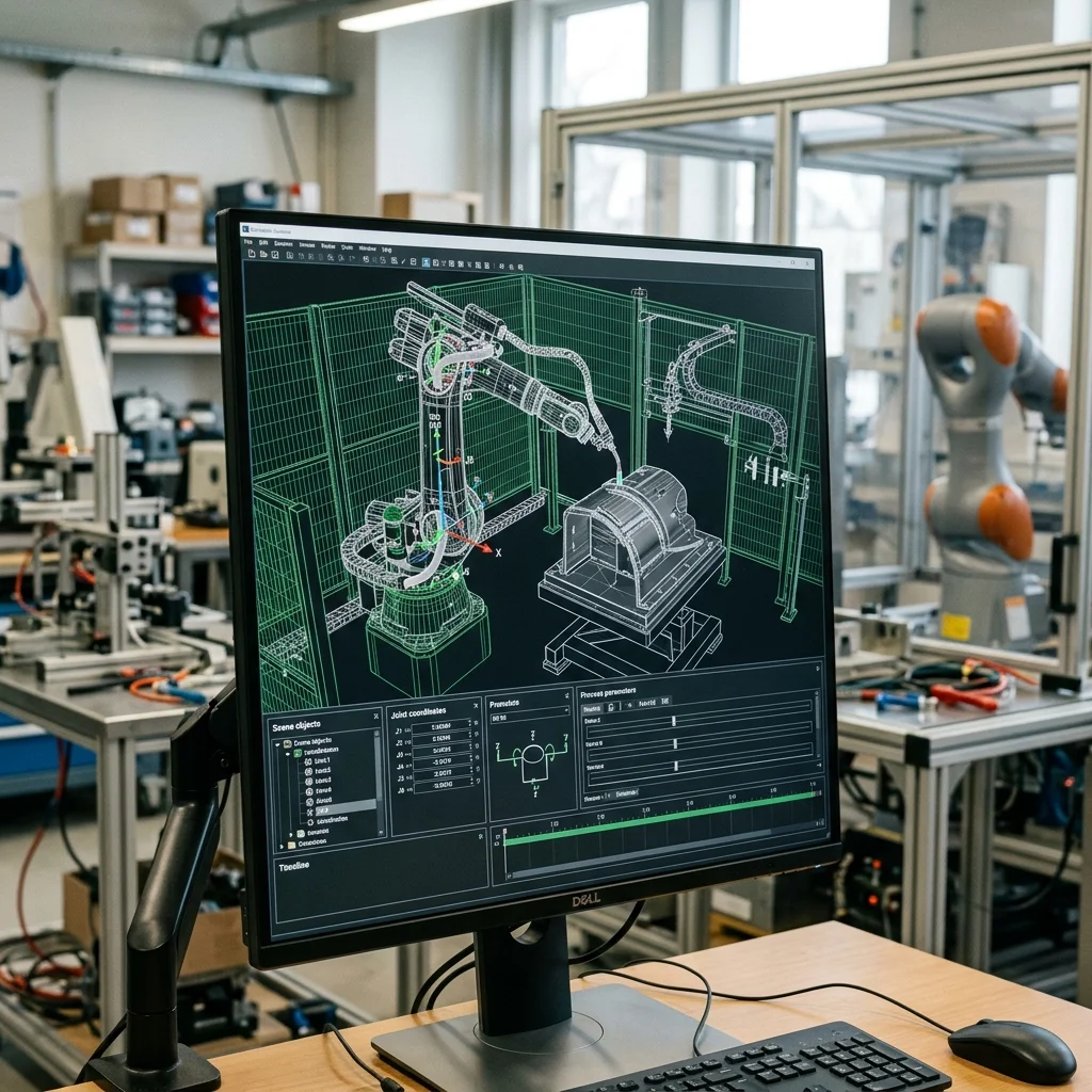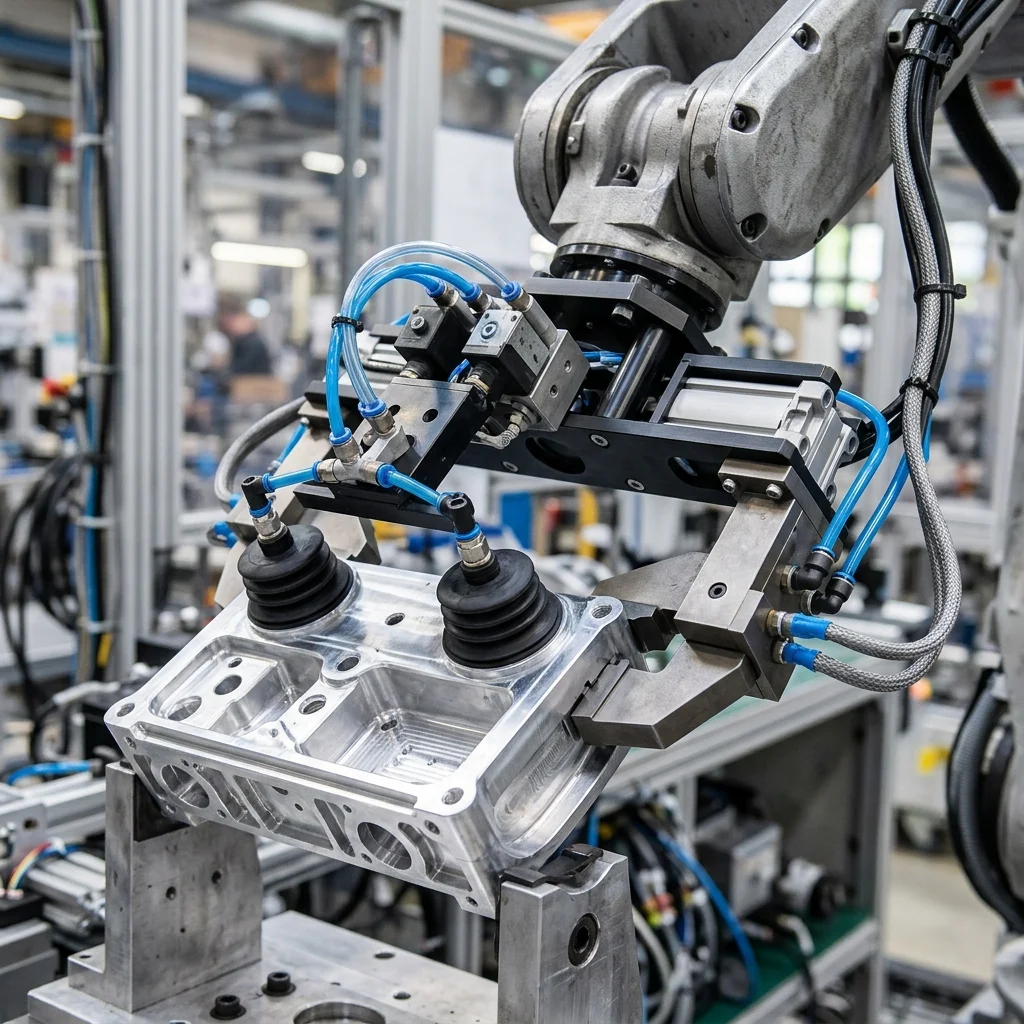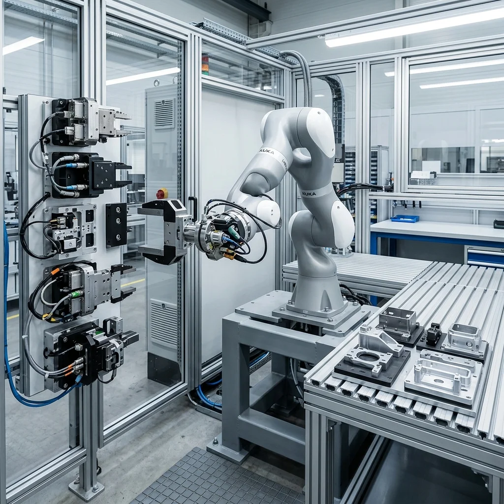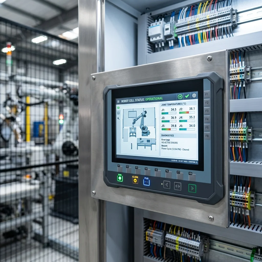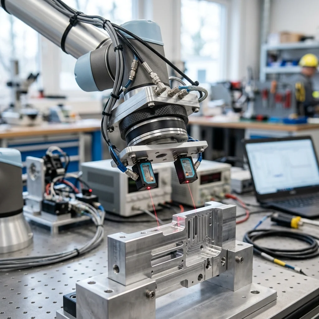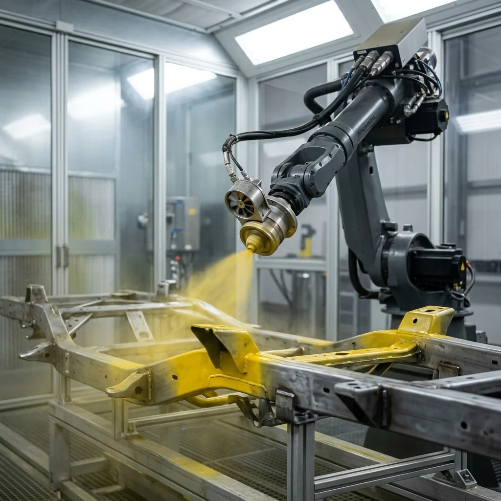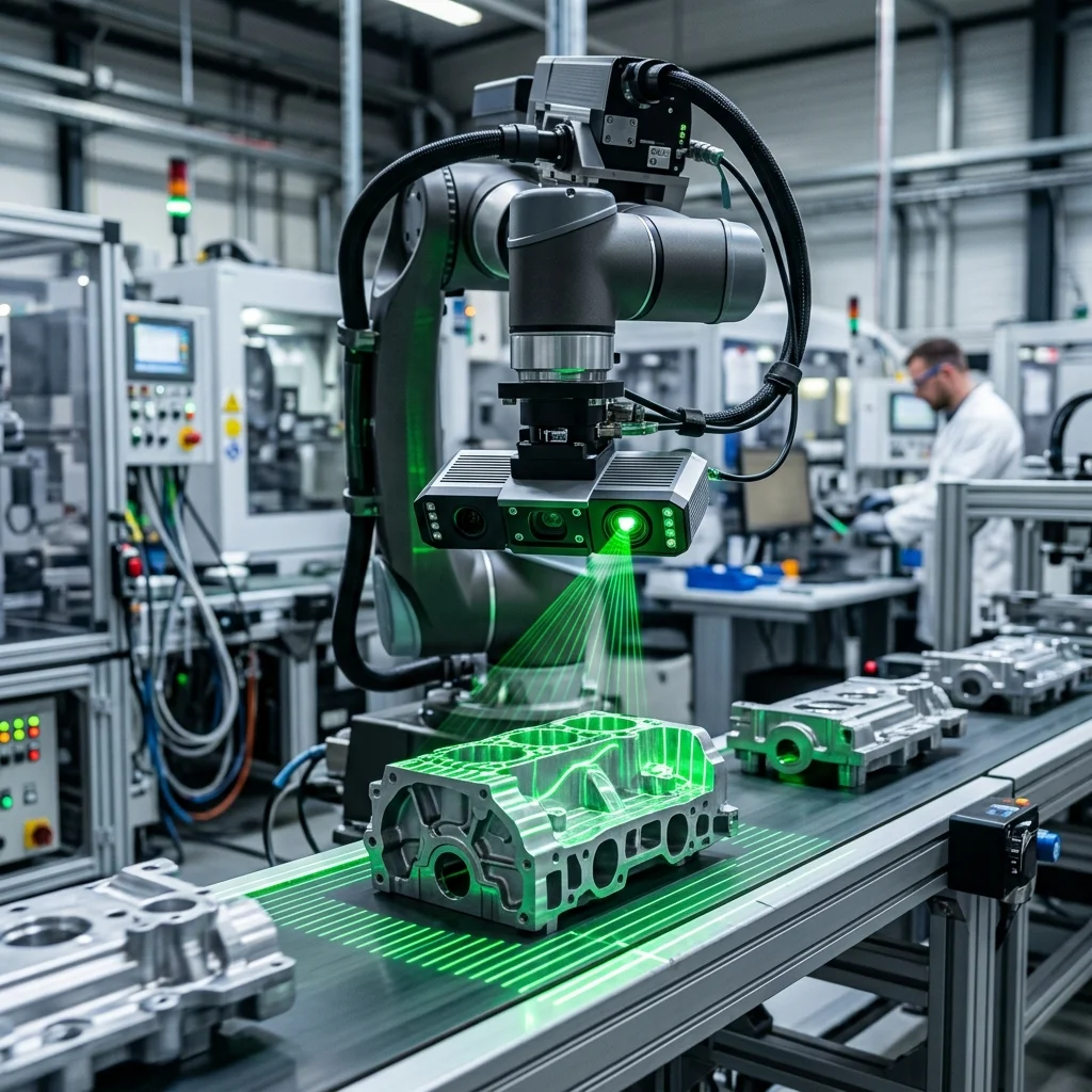
Integrating machine vision with industrial robotic cells allows for flexible part handling and assembly without rigid mechanical positioning fixtures. 2D vision systems are ideal for planar alignment, component presence verification, and barcode reading on flat surfaces, whereas 3D vision systems (using structured light or time-of-flight) are required for bin picking, depth profiling, and handling randomly oriented objects in three-dimensional space.
The Evolution of Optical Guidance in Industrial Automation
For decades, industrial automation relied on mechanical fixtures to position parts precisely before a robotic arm could interact with them. While reliable, this approach introduced significant tooling costs and made production lines inflexible. The introduction of machine vision has changed this dynamic by allowing robots to see and adapt to variations in part placement. Today, optical guidance is a fundamental component of modern manufacturing cells, enabling high-speed operations without rigid constraints.
Choosing between 2D and 3D vision systems is one of the most critical decisions in optical engineering. A 2D system captures a flat, two-dimensional image of the scene, analyzing contrast and edges to determine the X, Y coordinates and rotational orientation of a part. While highly effective for planar alignment, 2D vision lacks depth perception. A 3D vision system, on the other hand, captures the physical shape and volume of an object by generating a point cloud, which provides depth information (Z-axis) along with roll, pitch, and yaw angles.
Understanding the physical environment is essential when deploying either system. Ambient lighting, surface reflectivity, and part color can all interfere with image quality. While 2D systems are highly sensitive to lighting changes and require specialized backlights or ring lights, many 3D systems use structured light projections or lasers that are less affected by ambient factory lighting. Selecting the correct sensor technology ensures that the robot receives consistent, high-quality coordinate data.
Planar Applications and the Limits of 2D Vision
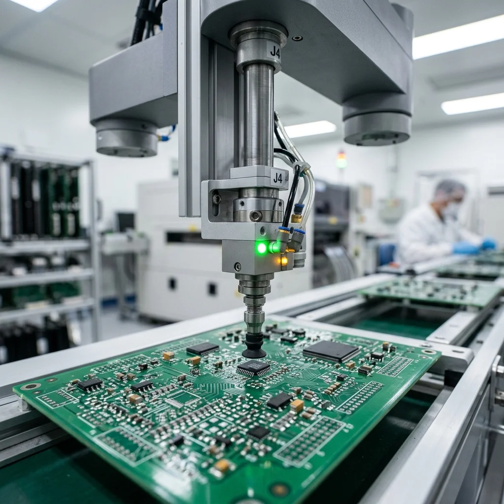
2D vision systems excel in applications where parts are uniform, flat, and presented on a single plane. Common tasks include label inspection, part presence verification, and sorting flat components on a conveyor belt. Because a 2D camera captures image data in pixels, the system relies on high contrast between the part and the background. When configured correctly, a 2D camera can determine a part's location in milliseconds, making it ideal for high-speed pick-and-place lines.
However, 2D vision falls short when parts overlap, vary in height, or tilt out of plane. Because a 2D camera cannot measure distance, any variation in part height changes the scale of the captured image, leading to calculation errors. For example, if a part is closer to the camera, it appears larger, which a 2D algorithm might interpret as a different component or a dimensional defect. This limitation makes 2D vision unsuitable for complex material handling like bin picking.
To mitigate these scale errors, system integrators must enforce strict mechanical constraints. Parts must be fed via vibrating trays or flat conveyors that prevent stacking. While these mechanical aids increase system complexity and cost, they allow 2D systems to achieve high throughput at a lower sensor cost. For simple, planar tasks, a well-lit 2D camera remains the most cost-effective solution for manufacturing plants.
3D Point Clouds, Structured Light, and Depth Profiling
When parts are randomly oriented, stacked in deep bins, or vary in height, 3D vision is required. 3D systems use different technologies to map depth. Structured light cameras project a known light pattern (like grids or stripes) onto the workpiece. A sensor captures the distortion of this pattern caused by the object's geometry, calculating a highly accurate 3D representation. This structured light approach is common in metrology and precision assembly.
Another common 3D technology is Time-of-Flight (ToF), which measures the time it takes for a light pulse to travel from the sensor to the object and back. ToF systems are excellent for larger volumes and longer distances, such as palletizing, though they generally offer lower resolution than structured light systems. The output of these 3D sensors is a point cloud, which is a collection of thousands of data points representing the surface coordinates of the scanned objects.
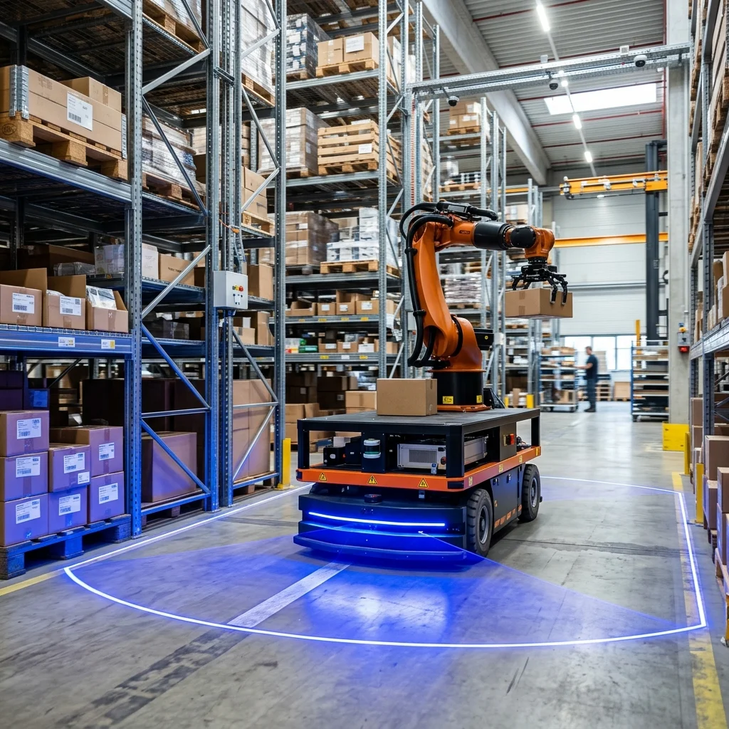
Analyzing a point cloud requires significant processing power. The vision software must filter out noise, segment the data to identify individual parts, and match the scanned shape against a CAD model of the workpiece. Once a match is found, the software calculates the optimal pick coordinate and sends it to the robot controller. This allows the robot to extract parts directly from a bin without collision, even if they are semi-structured or overlapping.
Calibration, Coordinate Mapping, and Hand-Eye Alignment
A machine vision system is useless unless its optical coordinates can be translated into physical robot coordinates. This process is called hand-eye calibration, and it maps the pixel or point cloud coordinates to the robot's physical coordinate system. There are two primary configurations: eye-in-hand, where the camera is mounted directly on the robot flange, and eye-to-hand, where the camera is mounted statically above the workspace.
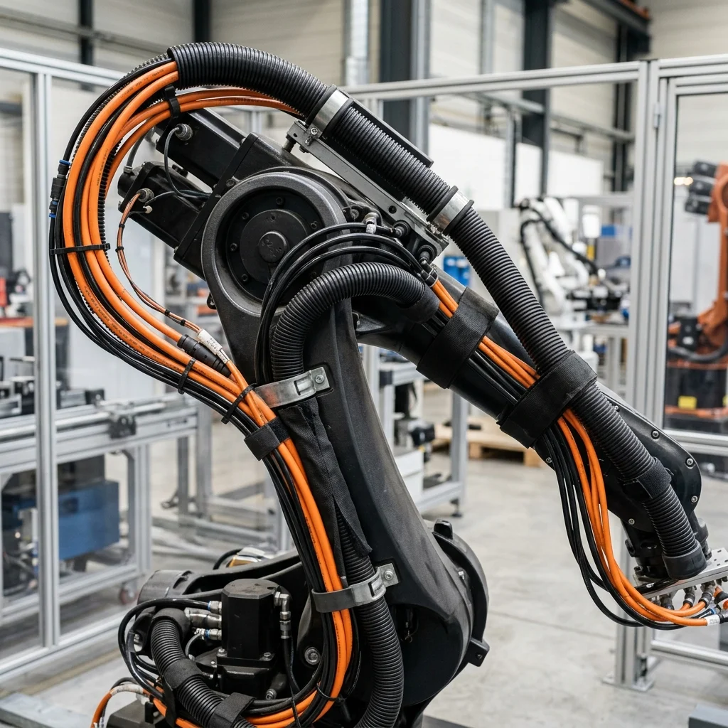
Eye-in-hand configurations offer flexibility because the robot can move the camera to capture images from different angles, which is useful for large workpieces. However, this setup subjects the camera to continuous acceleration forces, requiring robust mounting and cable management. Eye-to-hand systems are simpler and keep the camera isolated from motion, but the robot's arm can block the camera's view during parts of the cycle, which must be accounted for in the path programming.
Calibration must be performed periodically to correct for mechanical shifts, thermal expansion, or accidental bumps. Calibration targets, such as checkerboards or ball plates, are placed in the cell, and the robot moves through a sequence of taught positions while the camera captures images. The software calculates the transformation matrix, ensuring that a coordinate of (X: 150.5, Y: -200.2, Z: 50.1) in the vision system maps precisely to the physical location on the factory floor.
Choosing the Optimal System: A Practical Engineering Checklist
Before investing in a vision system, engineering teams should evaluate the specific requirements of the application to select the correct technology. First, determine the degrees of freedom required for the pick. If the part only moves in X, Y, and rotation, 2D is sufficient. If the part can tilt or is stacked, 3D is mandatory.
Second, evaluate the cycle time constraints. 2D systems process images in tens of milliseconds, whereas 3D point cloud generation and alignment can take up to a second or more. For ultra-high-speed packaging, 2D is often preferred. Third, assess the surface characteristics of the parts. Highly reflective, polished metal parts can cause glare that blinds optical sensors. In these cases, polarized filters or specialized laser line scanners are needed.
Finally, consider the total cost of ownership. 3D sensors are significantly more expensive than 2D cameras and require more advanced software programming. Integrators must weigh the cost of a 3D sensor against the mechanical complexity of feeding systems required to make a 2D sensor work. A balanced approach ensures the project meets both budget and performance goals.