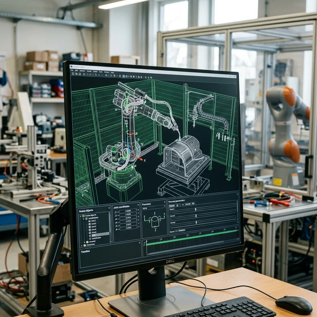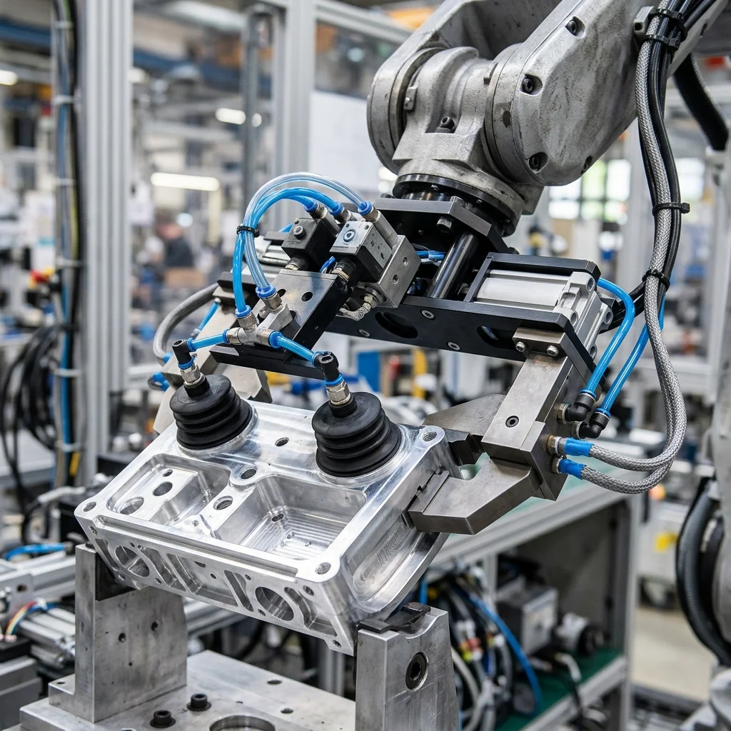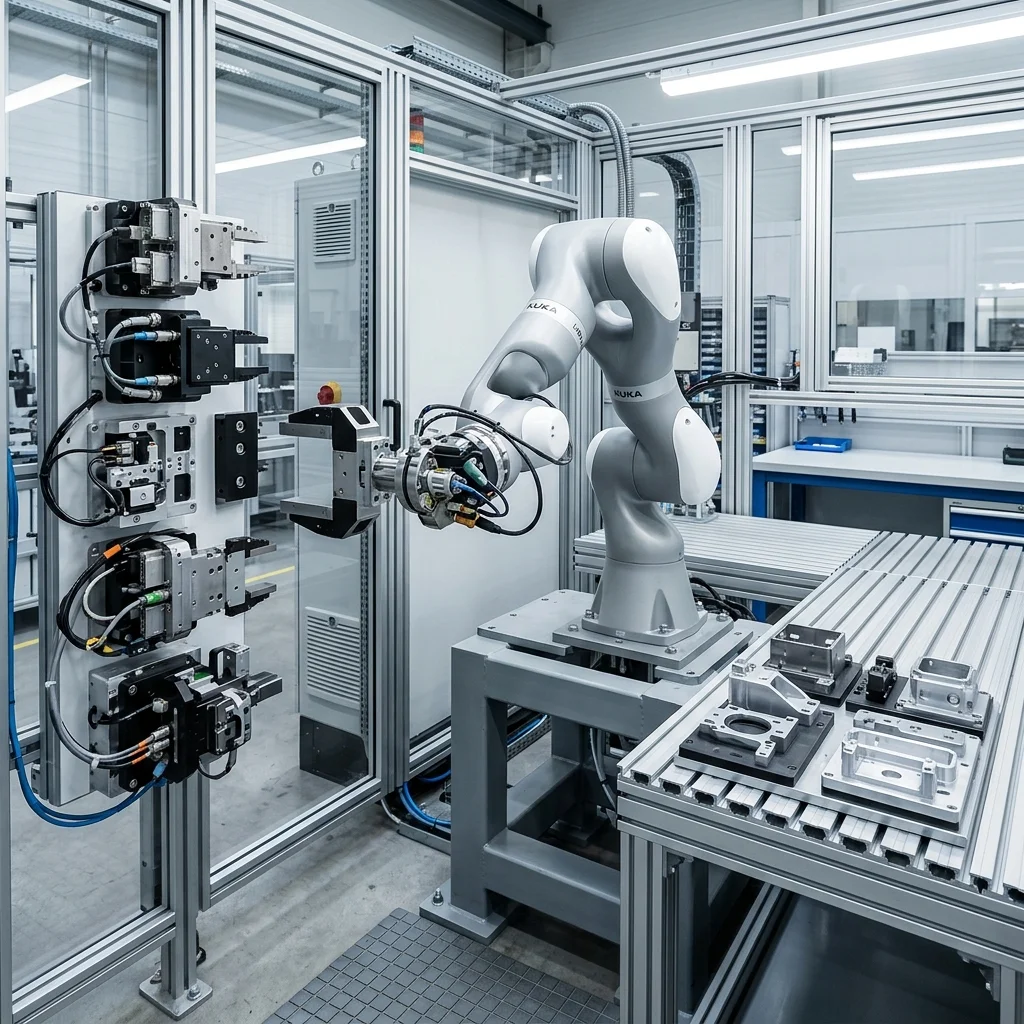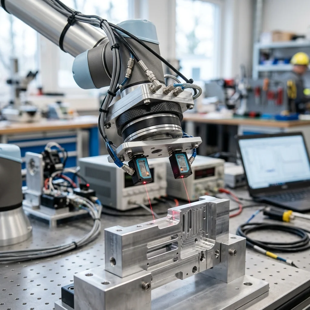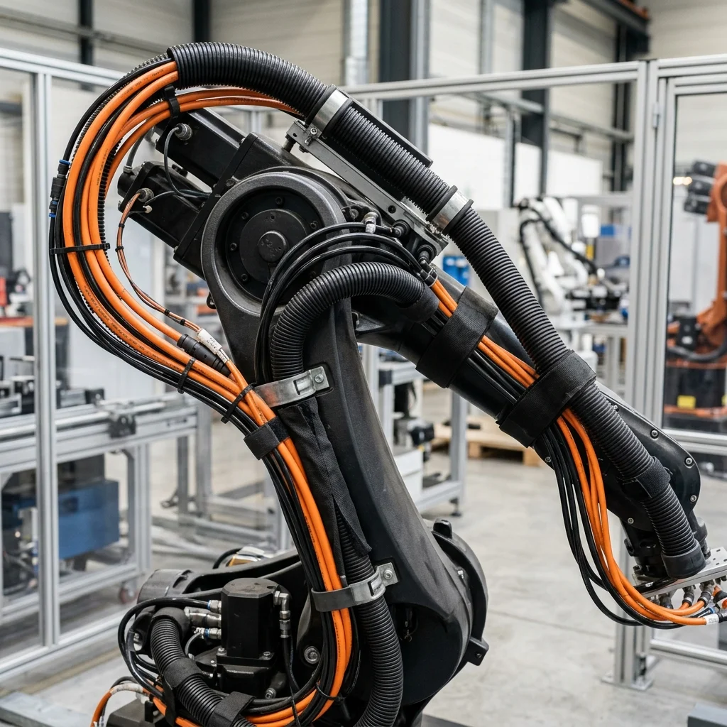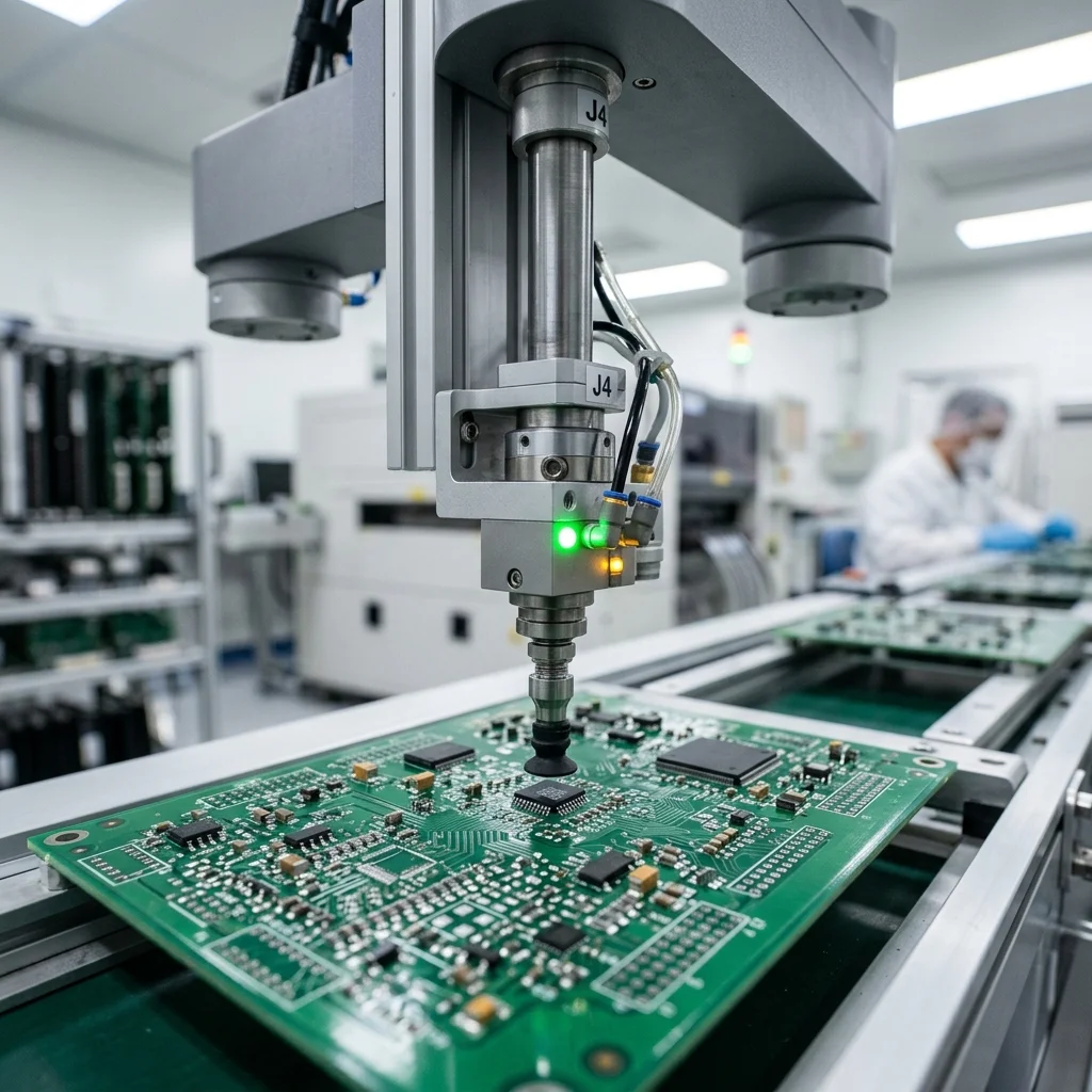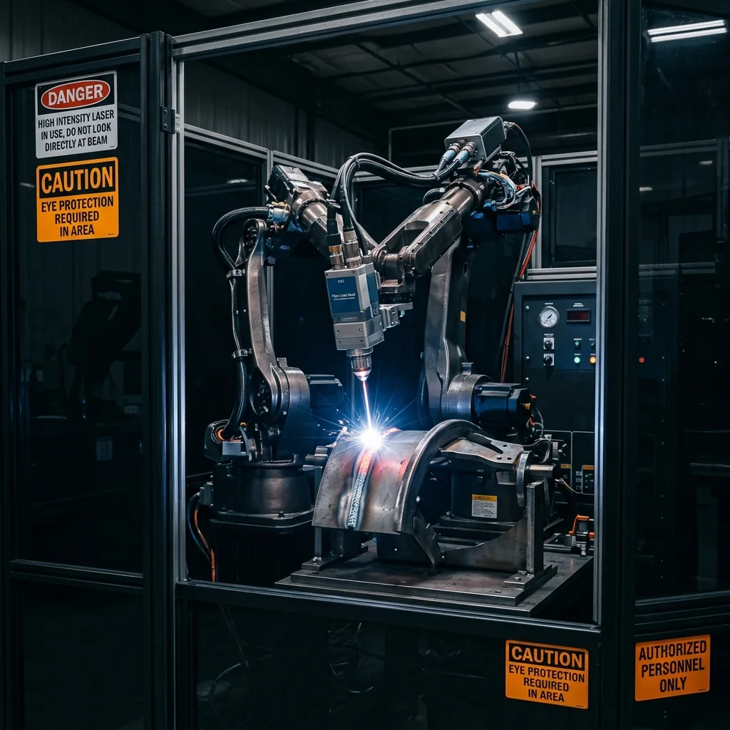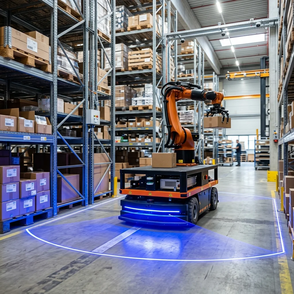
Integrating industrial robots with Programmable Logic Controllers (PLCs) and Human-Machine Interfaces (HMIs) requires establishing structured fieldbus handshaking protocols (such as PROFINET or EtherNet/IP). Rather than running isolated systems, the PLC acts as the cell coordinator while the robot executes motion routines as a slave device, exchanging critical state bytes to verify pick alignment, tool actuation, and emergency-stop coordination.
The Hierarchy of Cell Coordination: PLC as Master, Robot as Slave
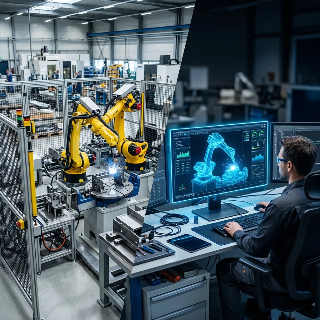
In a fully integrated industrial automation cell, clear control hierarchy is vital to prevent sequence conflicts. Modern engineering practices designate the Programmable Logic Controller (PLC) as the master cell coordinator, while the robot controller operates as an intelligent slave device. The PLC handles peripheral equipment such as safety gates, conveyors, indexing tables, and pneumatic clamps, issuing cycle command bytes to the robot when all interlocks are clear.
Under this architecture, the robot does not make decisions about when to move based on physical field sensors. Instead, sensors (like photoelectric part detectors and clamp position switches) are wired directly to the PLC's input modules. The PLC processes this logic and sets specific command bits inside the fieldbus communication packets. The robot controller continuously monitors these bits, executing the corresponding motion routine only when authorized by the master controller.
Attempting to program the robot as the master coordinator is a common integration mistake. While robot controllers are capable of processing basic logic and directly reading digital inputs, they lack the multi-threaded cycle scanning and extensive diagnostic capabilities of an industrial PLC. Keeping the robot focused on path execution while delegating cell logic to the PLC simplifies debugging, limits crash risks, and aligns with global automotive and manufacturing standards.
Fieldbus Protocols and Handshaking Bitmaps
Establishing communication between a PLC (such as Siemens S7-1500 or Allen-Bradley ControlLogix) and a robot controller (such as Fanuc R-30iB or KUKA KR C5) requires selecting an industrial network protocol. The two most common protocols are EtherNet/IP and PROFINET, both of which support high-speed, deterministic data exchange over industrial Ethernet cables. For older legacy systems, PROFIBUS or DeviceNet may be used, though they offer much lower bandwidth.
Communication is structured using input and output byte arrays, commonly called handshaking bitmaps. A standard handshaking sequence uses dedicated bits to coordinate movement. For example, before the PLC indexes a turntable, it must verify the robot is in a safe position by reading the 'At Home' or 'At Safe' bit. Once the table has finished indexing and is locked, the PLC sets a 'Start Process' bit, signaling the robot to begin its work cycle. These bits must be interlocked on both controllers to prevent collisions.
A robust handshake design also includes integer-based program select codes (commonly called Group Inputs/Outputs or PGNO). Instead of using digital inputs to trigger specific paths, the PLC writes an integer value representing the recipe number directly to a register on the robot. The robot reads this register, loads the corresponding tool path from its memory, and writes back the same integer to the PLC as an echo confirmation before executing the first move. This handshake prevents the robot from executing the wrong path on a part variant.
HMI Design for Diagnostics and Error Recovery
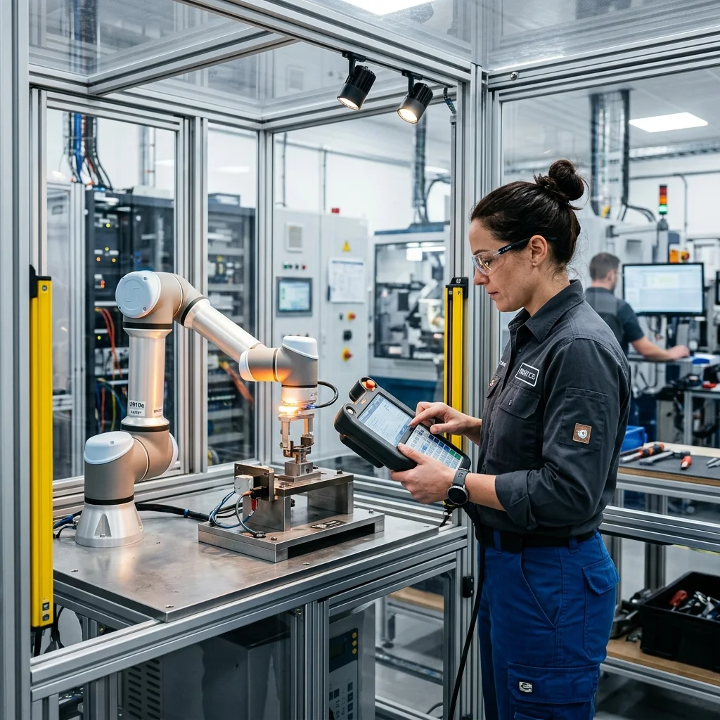
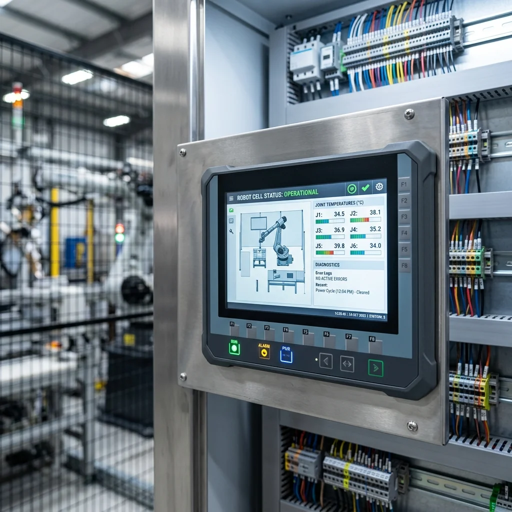
A key requirement for any robotic cell is that the operators must be able to clear faults and recover the system without using the robot teach pendant or opening the programming software. This is achieved by designing comprehensive diagnostic screens on the Human-Machine Interface (HMI). The HMI should display the exact state of the PLC-robot handshake, allowing technicians to see which interlock bit is holding up the sequence.
To provide useful feedback, the robot controller must send its active error codes directly to the PLC. Modern controllers support mapping alarm registers to fieldbus outputs. The PLC reads these registers and matches the error code (e.g., 'SRVO-062 Torque Limit Excess' on a Fanuc robot) against a database of text strings, displaying a clear troubleshooting message on the HMI. This reduces diagnostic times from hours to seconds.
Error recovery routines are another critical feature of the HMI. If a safety gate is opened during a cycle, the robot enters an emergency stop state, halting its path. The HMI should guide the operator through the recovery sequence: closing the gate, resetting safety relays, and using HMI buttons to command the robot to retract safely to its home position in manual mode. Designing these automated recovery paths prevents operators from making jogging mistakes that cause crashes.
Safety PLC Integration and PROFIsafe Communication
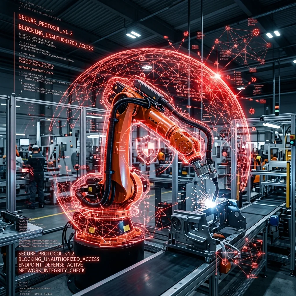
In modern automated cells, safety logic is separated from standard control logic to prevent software corruption from bypassing safety devices. This is accomplished by using a Safety PLC alongside standard I/O modules. Emergency stops, gate switches, light curtains, and safety scanners are wired directly to yellow safety input modules, and safety logic is programmed in a restricted, password-protected task.
To simplify wiring, safety signals can be transmitted to the robot controller over the same Ethernet cable as standard control data using safety protocols like PROFIsafe or CIP Safety. These protocols use redundant data packets, checksums, and timeout checks to ensure that safety-critical signals (such as e-stops and speed limits) are transmitted reliably. This eliminates the need for complex, hardwired safety relays and interposing contactors.
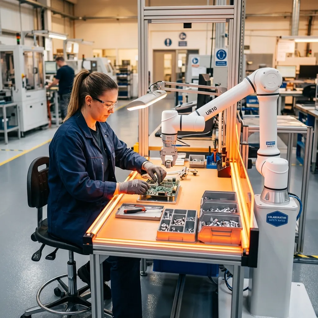
Through PROFIsafe, the Safety PLC can dynamically control the robot's safety states. For example, if an operator approaches a collaborative zone, the Safety PLC can trigger the robot's Safety-Rated Monitored Speed (SLS) state, slowing the arm down to a safe speed. If the operator steps closer and breaks a light curtain, the Safety PLC triggers a Safe Stop 1 (SS1), bringing the robot to a controlled stop before removing power, protecting both the operator and the mechanical gears.
Integration and Handshake Verification Checklist
Before executing the first automatic cycle, the integration team must run through a checklist to verify the PLC-robot interface. First, test every emergency stop button individually, ensuring it trips the safety relays and cuts power to the robot's motor actuators. Second, verify the communication mapping by toggling each input and output bit manually on the PLC and confirming the status change on the robot controller.
Third, test the program selection handshake by writing various recipe integers from the PLC and verifying that the robot echoes the correct code and loads the corresponding OLP program. Finally, simulate communication failure by disconnecting the Ethernet cable during a slow move; the robot must stop immediately due to a heartbeat timeout error, demonstrating that the system will fail safely under a network disruption.