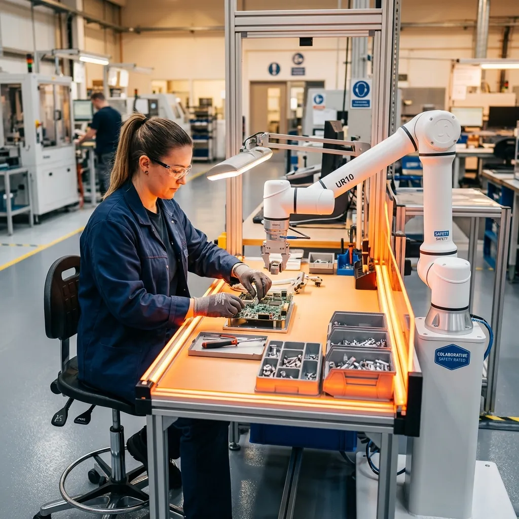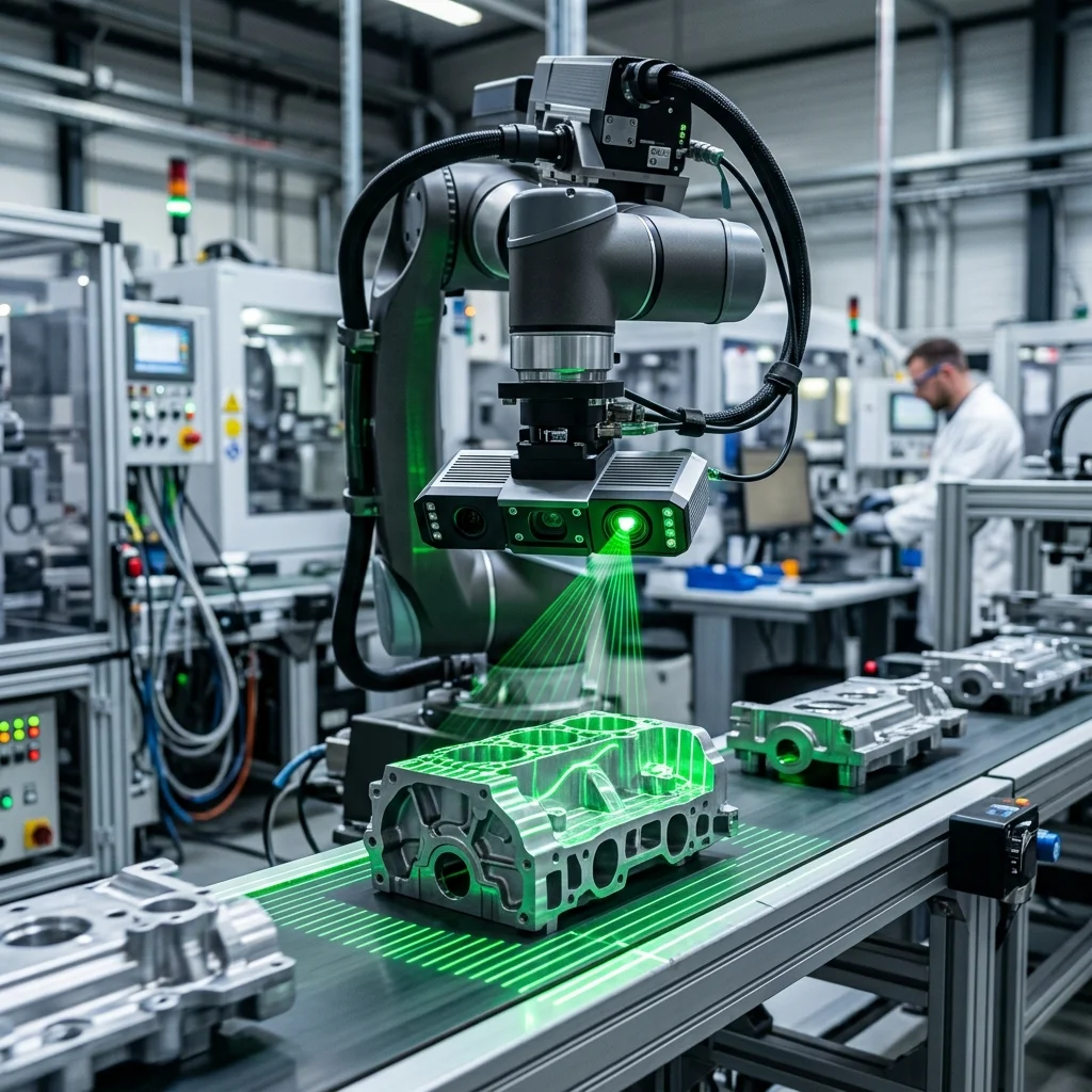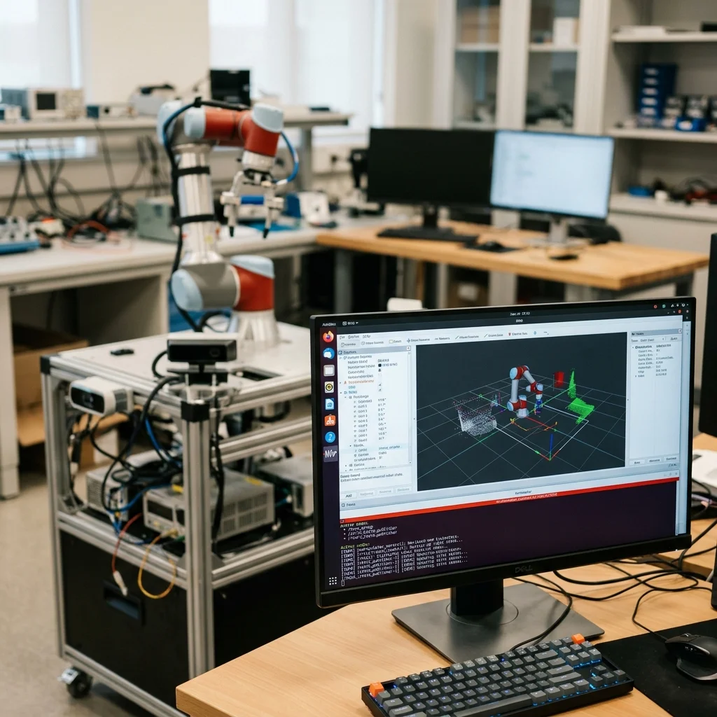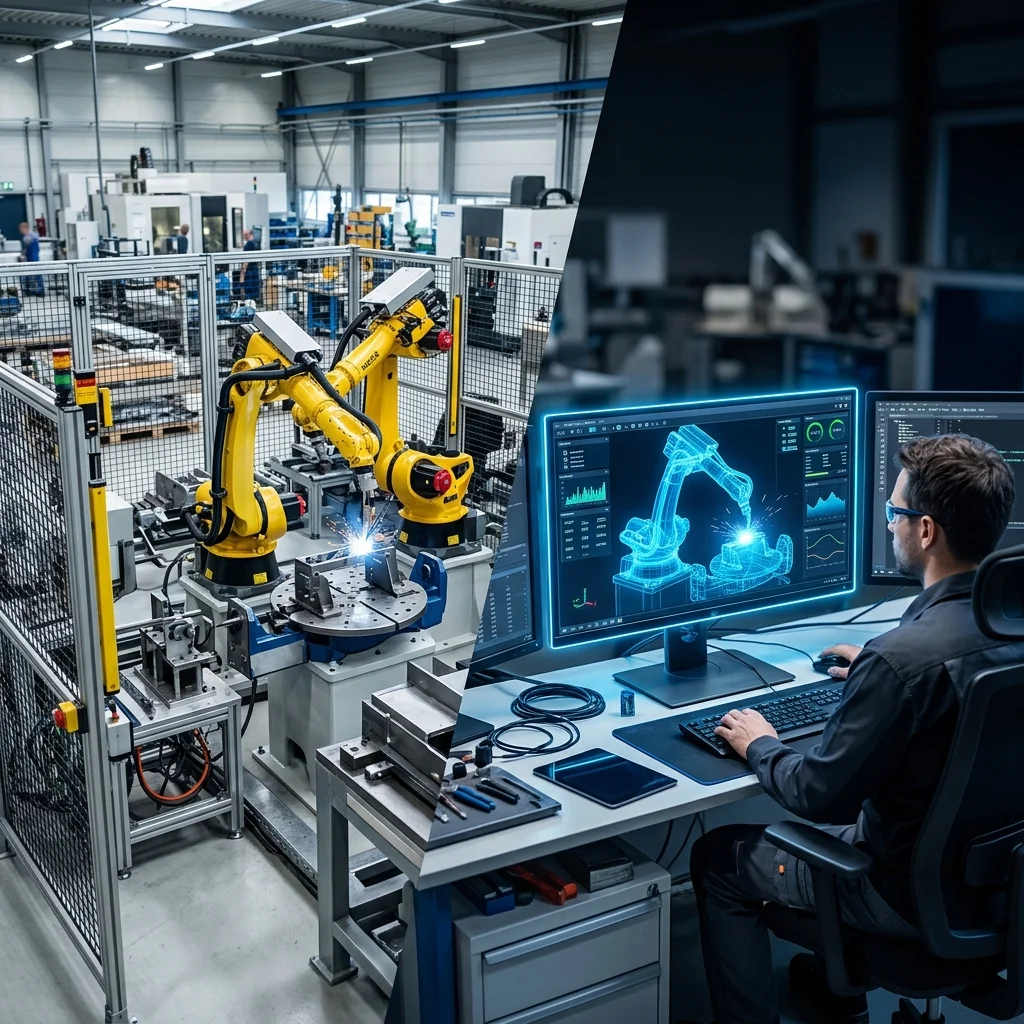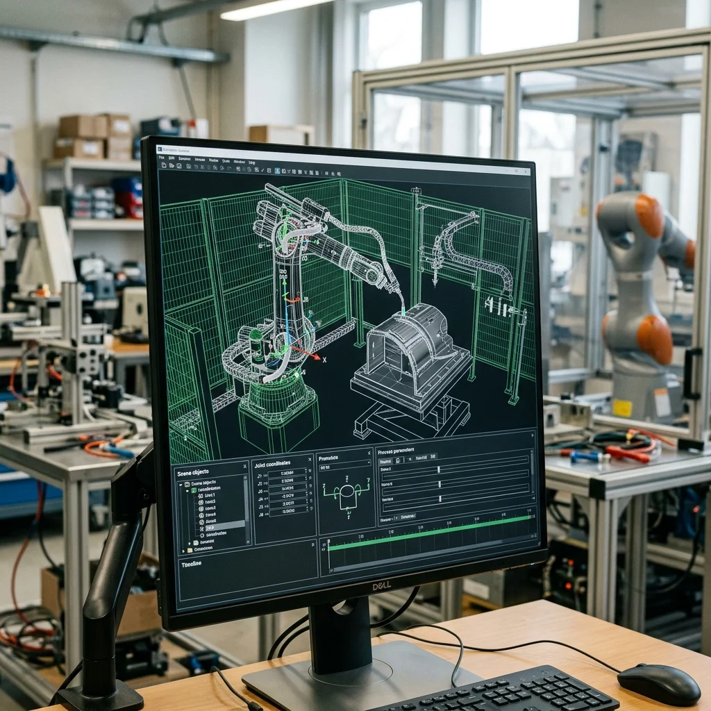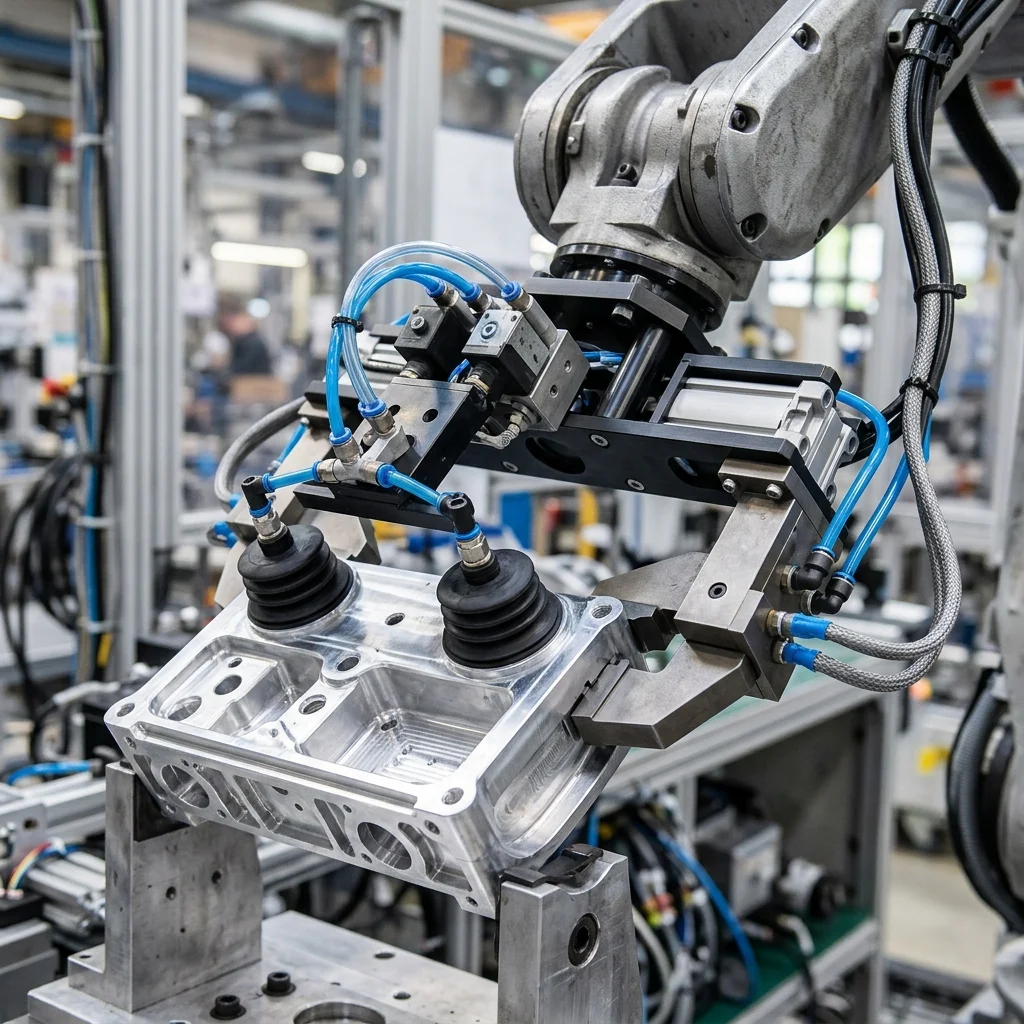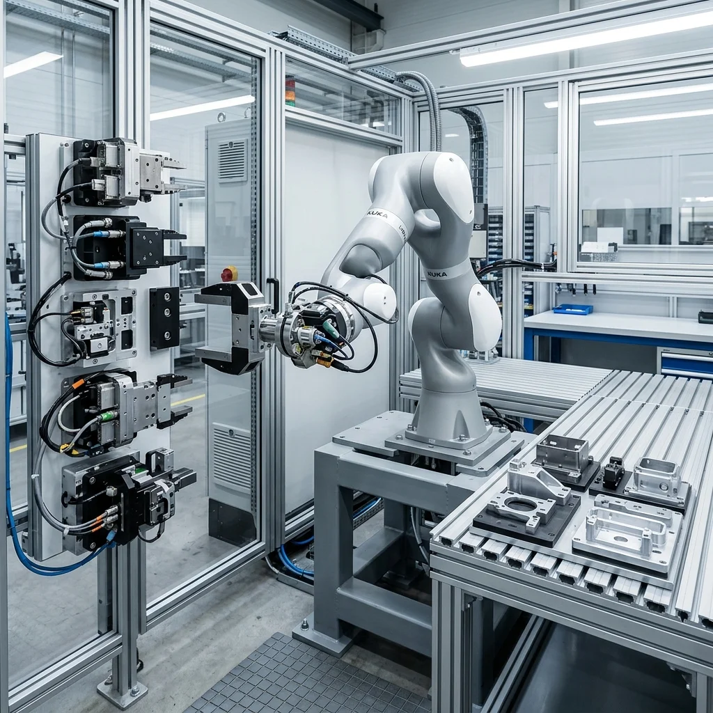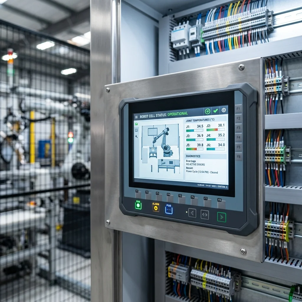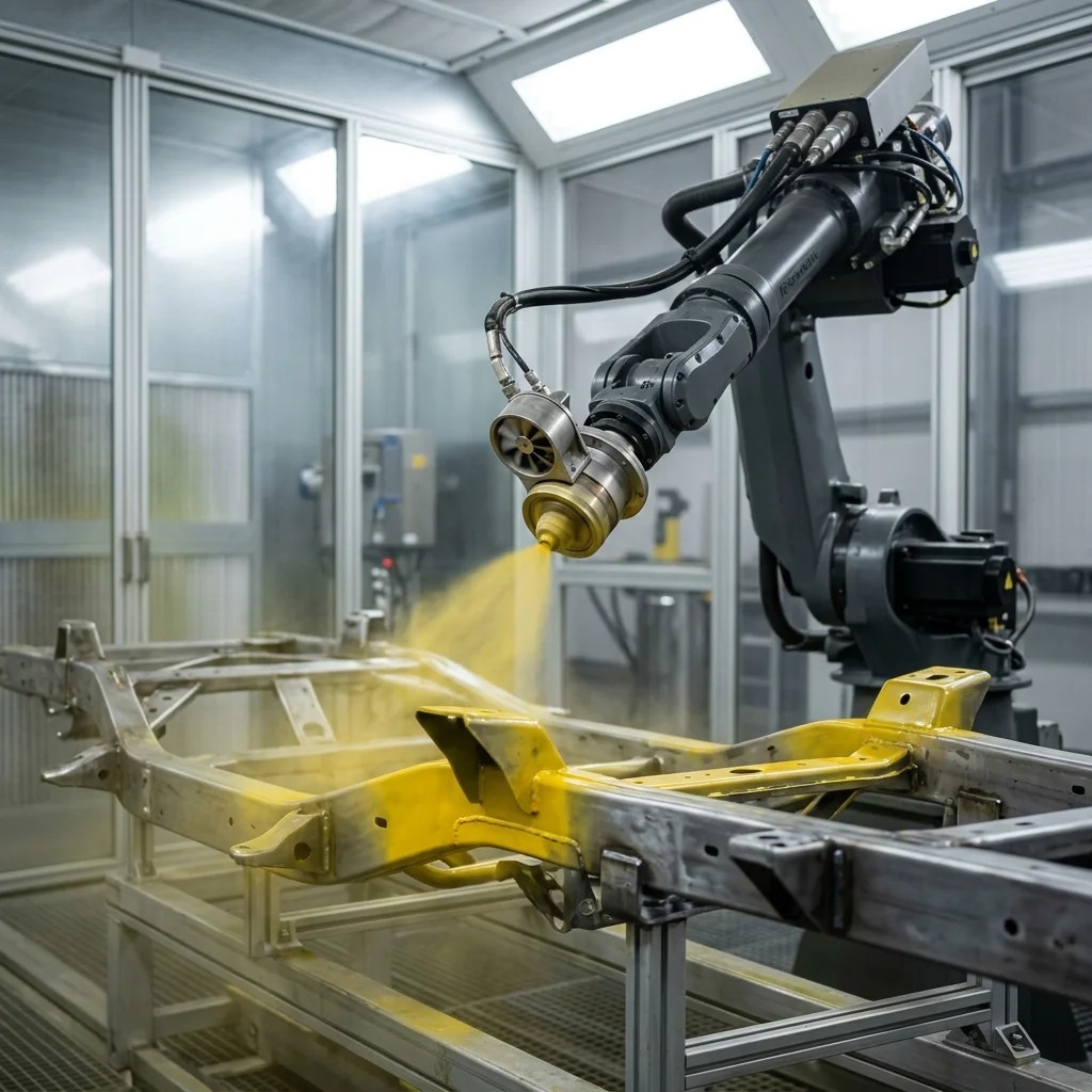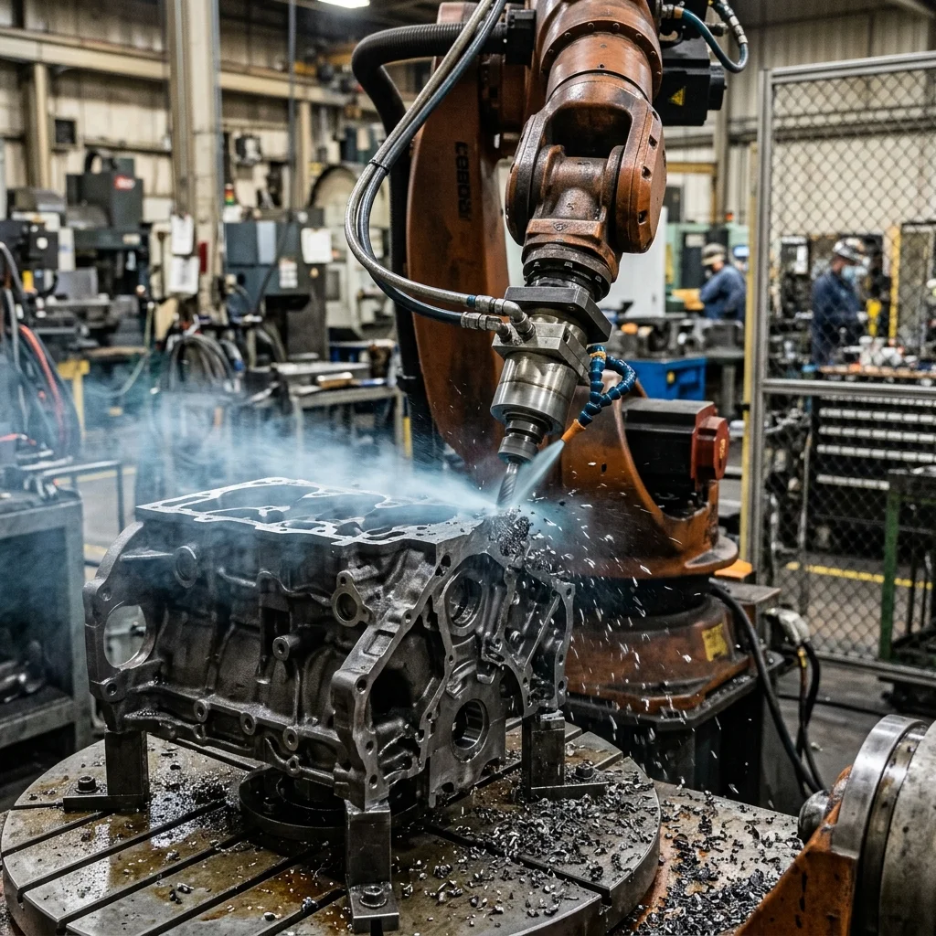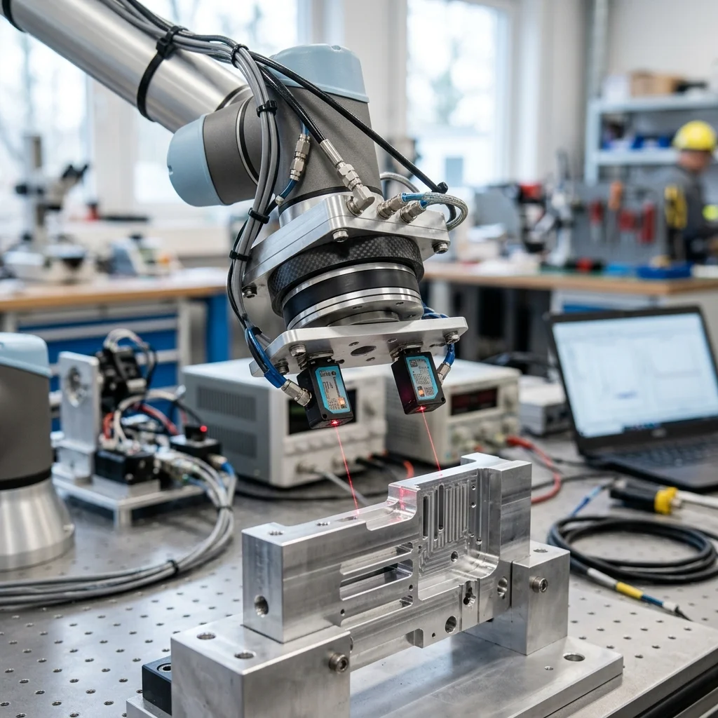
Implementing force-torque (F/T) sensors at the robot tool flange introduces tactile feedback, allowing robotic arms to perform high-precision assembly, polishing, and deburring tasks. By measuring forces and moments along all three orthogonal axes (Fx, Fy, Fz, Mx, My, Mz), the control loop can adjust the robot's trajectory in real time to maintain a constant contact force or verify parts fitment.
The Need for Tactile Sensing in Robotics
Standard industrial robots are position-controlled machines. They excel at moving to exact coordinates with high repeatability. However, they are blind to the forces they apply to their environment. If a part is slightly out of tolerance or misaligned, a position-controlled robot will continue its path, exerting excessive force that can damage the workpiece, the gripper, or the robot itself.
Integrating a force-torque (F/T) sensor at the tool flange solves this limitation by providing the robot controller with tactile feedback. The sensor measures the reaction forces and moments generated when the tool contacts a surface, allowing the robot to feel its way through a task. This capability is essential for precision tasks like insert mating, screw driving, grinding, and polishing.
Adding force sensing transitions the robot from a rigid manipulator into an adaptable tool. For instance, in a polishing application, the robot can adjust its path dynamically to maintain a constant contact force against a curved surface, compensating for variations in the workpiece shape. This force-feedback capability reduces scrap rates and enables the automation of tasks that were previously limited to manual operators.
The Physics of Multi-Axis Force-Torque Sensors
A standard industrial F/T sensor is a 6-axis device. It measures three force components (Fx, Fy, Fz) representing translation forces, and three torque components (Mx, My, Mz) representing rotational moments. The sensor is physically mounted between the robot's mounting flange and the end effector, ensuring that all forces acting on the tool are routed through the sensor's measuring body.
Most F/T sensors use strain gauges or silicon-based capacitive sensors mounted on internal flexure beams. When an external force is applied, the flexures experience microscopic deformations, changing the electrical resistance or capacitance of the sensors. The onboard electronics amplify and digitize these signals, translating them into calibrated force and torque values using a factory calibration matrix.
For high-speed control loops, the sensor must transmit data with low latency. Industrial F/T sensors typically export data over high-speed communication interfaces like EtherCAT, PROFINET RT, or dedicated analog channels, with update rates ranging from 1 kHz to 8 kHz. This high-frequency feedback allows the robot's motion controller to make micro-adjustments to the joint motors before forces exceed safe limits.
Active vs. Passive Compliance: Force Control Strategies
When designing a force-guided application, engineers must choose between active compliance and passive compliance. Passive compliance relies on mechanical devices, such as remote center compliance (RCC) units or spring-loaded tool holders, to absorb misalignments. While simple and cheap, passive compliance is inflexible and cannot monitor the process for quality control.
Active compliance utilizes the F/T sensor data to modify the robot's path in real time. The robot controller runs closed-loop force control algorithms, such as impedance control or admittance control. Impedance control adjusts the robot's joint torques based on the measured deflection, acting like a virtual spring. Admittance control reads the forces and calculates a velocity offset, moving the robot in the direction of the force to reduce contact pressure.
Implementing active compliance requires advanced software programming. Integrators must define force thresholds, stiffness parameters, and feedrate limits for each axis. For example, during a search routine to find a hole, the robot moves slowly in the Z-axis until the force exceeds a touch threshold (e.g., 5 Newtons), indicating contact. The robot then executes a spiral search path, monitoring forces until the Z-force drops, indicating the tool has aligned with the hole.
Sensor Calibration and Gravity Compensation
Before an F/T sensor can be used for force control, the controller must isolate the process forces from the static weight of the end effector. Because the gripper and workpiece have mass, they exert gravitational forces and moments on the sensor that change as the robot changes its orientation. Without compensation, the sensor will read these gravity loads as contact forces.
Gravity compensation requires calibrating the tool's mass properties. The integration team must input the tool's mass, coordinates of its center of gravity (CoG), and inertia matrix into the force control software. The controller uses this data, along with the robot's kinematic model, to calculate and subtract the expected gravity forces for any given tool orientation, zeroing out the sensor readings.
Calibration is typically performed automatically through a software utility. The robot moves the tool through a series of slow, varied orientations while the sensor records forces. The software runs a regression algorithm to estimate the tool mass and CoG coordinates. Regular verification of this calibration is recommended, as any changes to the tooling (like adding sensors or changing gripper jaws) will impact the accuracy of the gravity model.
Force-Guided Assembly Checklist
When implementing a force-guided assembly cell, mechatronics engineers should follow a structured deployment checklist. First, select a sensor with a measurement range that matches the process forces, ensuring the maximum expected load does not exceed the sensor's overload limit, which can permanently deform the internal flexures.
Second, verify that the sensor's mounting adapter is rigid and machined to precise flatness tolerances to prevent introducing internal mechanical stress. Third, program force limits in the robot's background task that immediately trigger a category 0 stop if forces exceed a safe threshold, protecting the cell from programming errors. Finally, verify the gravity compensation by moving the robot in manual mode and checking that the sensor reading remains close to zero across all orientations.