Designing a reliable dynamic dresspack (cable management system) for 6-axis industrial robots requires managing the continuous bending, twisting, and tension forces acting on cables and pneumatic hoses. By using high-flex robotic cables, corrugated conduits with spring retraction systems, and proper anchor brackets, engineers can prevent cable wear, minimize torsional stress, and eliminate the leading cause of robot downtime.
Cable Management as the Leading Cause of Robot Downtime
In industrial robotics, mechanical and software components are highly reliable. Modern servo motors, gearboxes, and controllers are designed to run for tens of thousands of hours without failure. Instead, the most common source of unscheduled downtime on the factory floor is cable and hose failure. The system of cables, hoses, and conduits that routes power, air, and signals to the end effector is called a dresspack, and its design requires careful mechatronics engineering.
During normal operation, a 6-axis robot twists, bends, and accelerates at high rates, subjecting the dresspack to complex mechanical stresses. Standard industrial cables are not designed for this environment and will quickly fail due to copper fatigue, insulation wear, or internal conductor breaks. A broken cable halts production and can be difficult to diagnose, as internal breaks can cause intermittent faults.
To prevent these failures, dresspacks must be designed as dynamic systems that support and guide the cables through the robot's entire work envelope. This involves selecting specialized high-flex materials, designing routing paths that distribute torsional stress, and implementing tension-control mechanisms to prevent the conduit from snagging on cell fixtures.
Anatomy of a Modern Dynamic Dresspack System
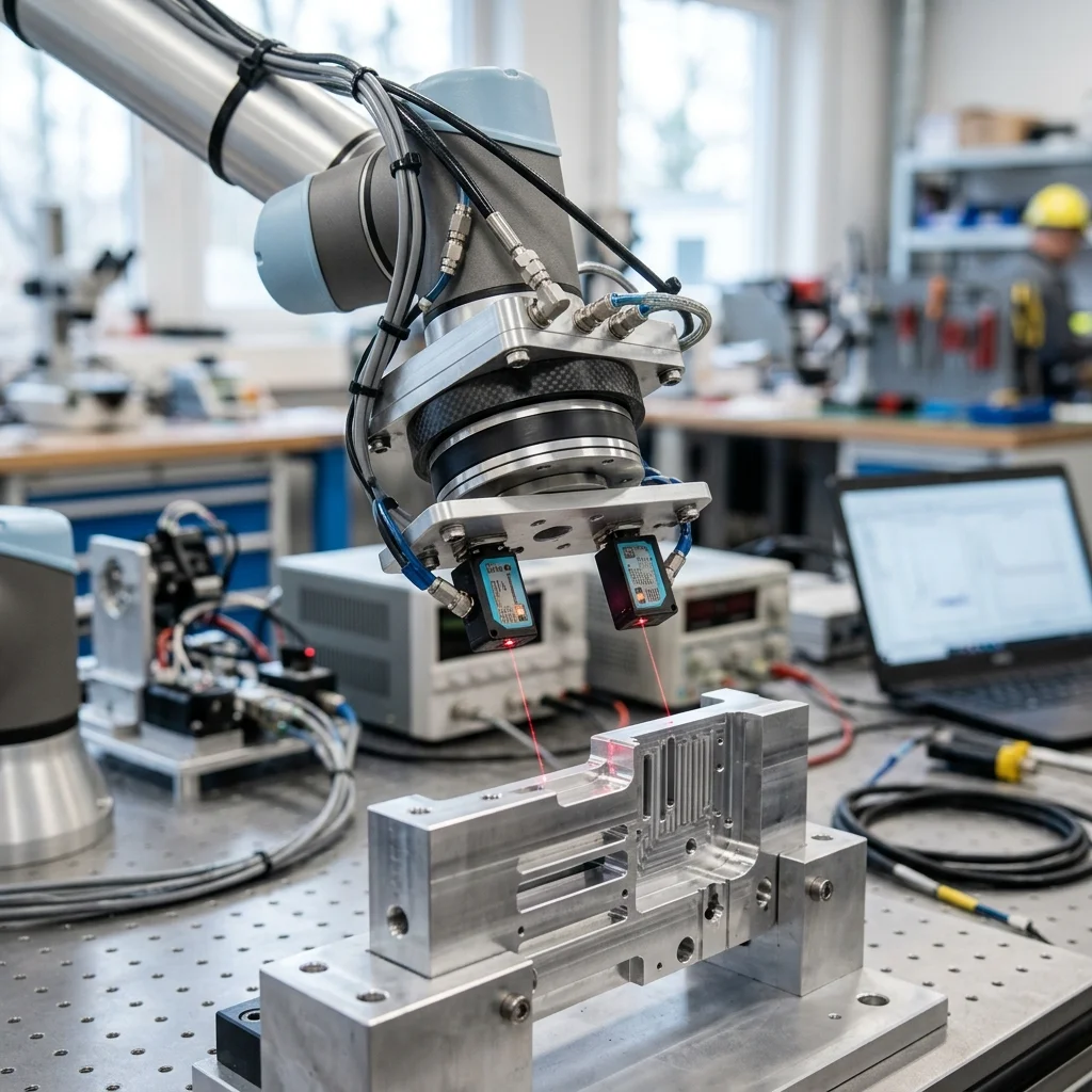
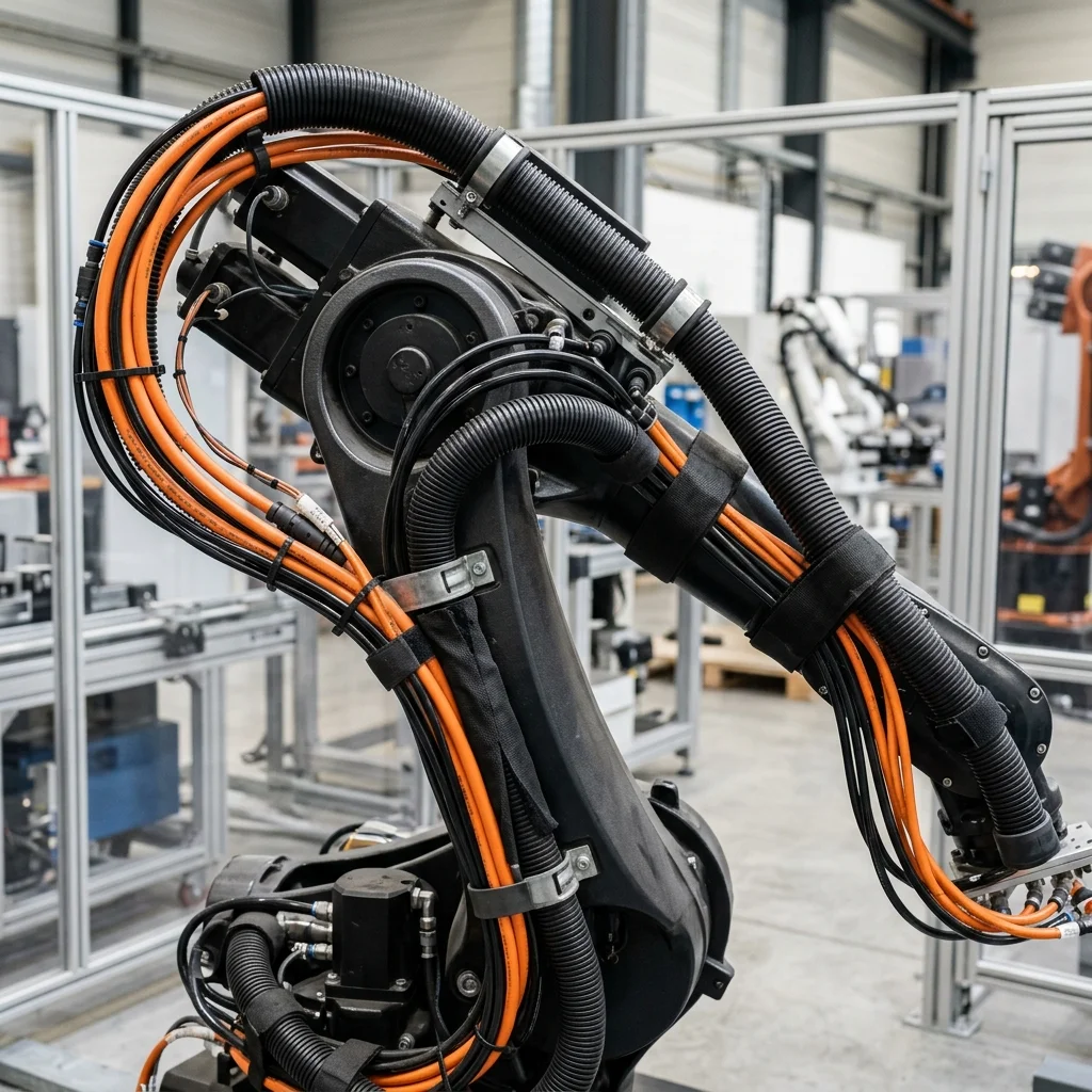
A dynamic dresspack consists of several components working together to protect the internal utilities. The outer layer is typically a corrugated plastic conduit (often made from specialized polyamides) that provides impact resistance and holds the cable bundle. The conduit is supported by swivel joints and mounting brackets anchored to specific locations on the robot arm (usually at Axis 1, Axis 3, and Axis 6).
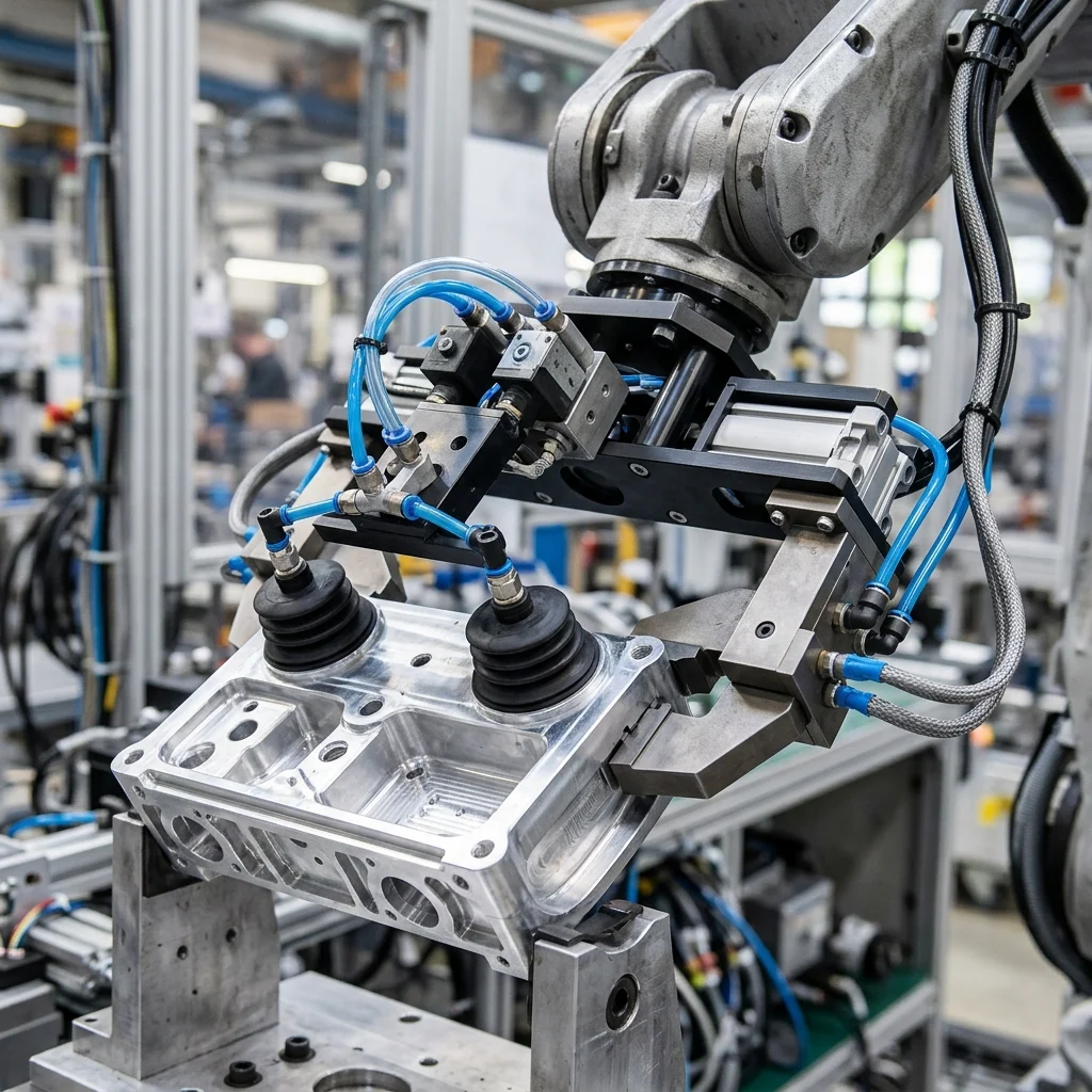
Inside the conduit, cables and hoses are arranged using internal separators. These separators keep cables from twisting around each other and prevent friction wear. Cables must be laid flat without tension or compression. Standard components in a dresspack bundle include robot-rated power cables, shielded sensor wires, Ethernet communication lines, and reinforced polyurethane hoses for compressed air.
A critical component for 6-axis robots is the spring retraction system, often mounted on Axis 3 or 4. As the robot bends, the distance between the anchor points changes. The retraction system uses internal springs to pull back the slack conduit, keeping it close to the robot arm. This prevents the conduit from forming large loops that can snag on safety fencing, workpieces, or fixtures.
Selecting High-Flex Robotic Cables and Materials
Standard industrial cables use copper conductors with standard PVC jackets, which are too stiff for dynamic applications. High-flex robotic cables utilize fine-stranded copper wires, often wound in bundles with a short pitch to reduce stress during twisting. The insulation and outer jacket are made from specialized polyurethanes (PUR) or thermoplastic elastomers (TPE) that offer high wear resistance and flexibility.
Robotic cables are rated based on their flex life and twisting tolerance. A standard specification for a robotic cable is the capability to withstand over 10 million bending cycles and torsional twisting of ±180 degrees per meter. Shielding is another consideration; communication lines must use high-density braided copper shielding with low-friction wraps to maintain signal integrity without introducing stiffness.
Pneumatic hoses must also be rated for continuous flexing. Standard polyurethane hoses can kink or harden over time, restricting airflow and placing stress on connections. Integrators should specify high-flex, hydrolysis-resistant polyurethane hoses that maintain their flexibility across a wide temperature range, preventing pressure drops and leakage in the cell.
Dynamic Routing Principles and Axis 6 Rotation Solutions
When layout out a dresspack, engineers must follow several routing principles. The first rule is to respect the minimum bend radius of the cables and conduit, which is typically set at 8 to 10 times the outer cable diameter. Bending a cable sharper than its limit concentrates stress, leading to conductor failure.
The second rule is to distribute torsional stress over a long length. Axis 6 (the tool flange) undergoes the most rotation, often turning more than 360 degrees. To prevent twisting forces from concentrating at the connection point, the dresspack should incorporate a loop or a rotary union. Rotary unions pass electrical signals and air through rotating contact plates, allowing the flange to rotate indefinitely without twisting any cables.
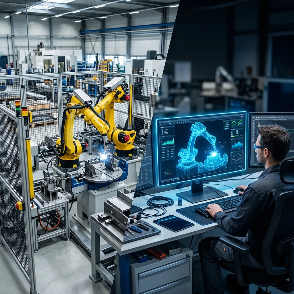
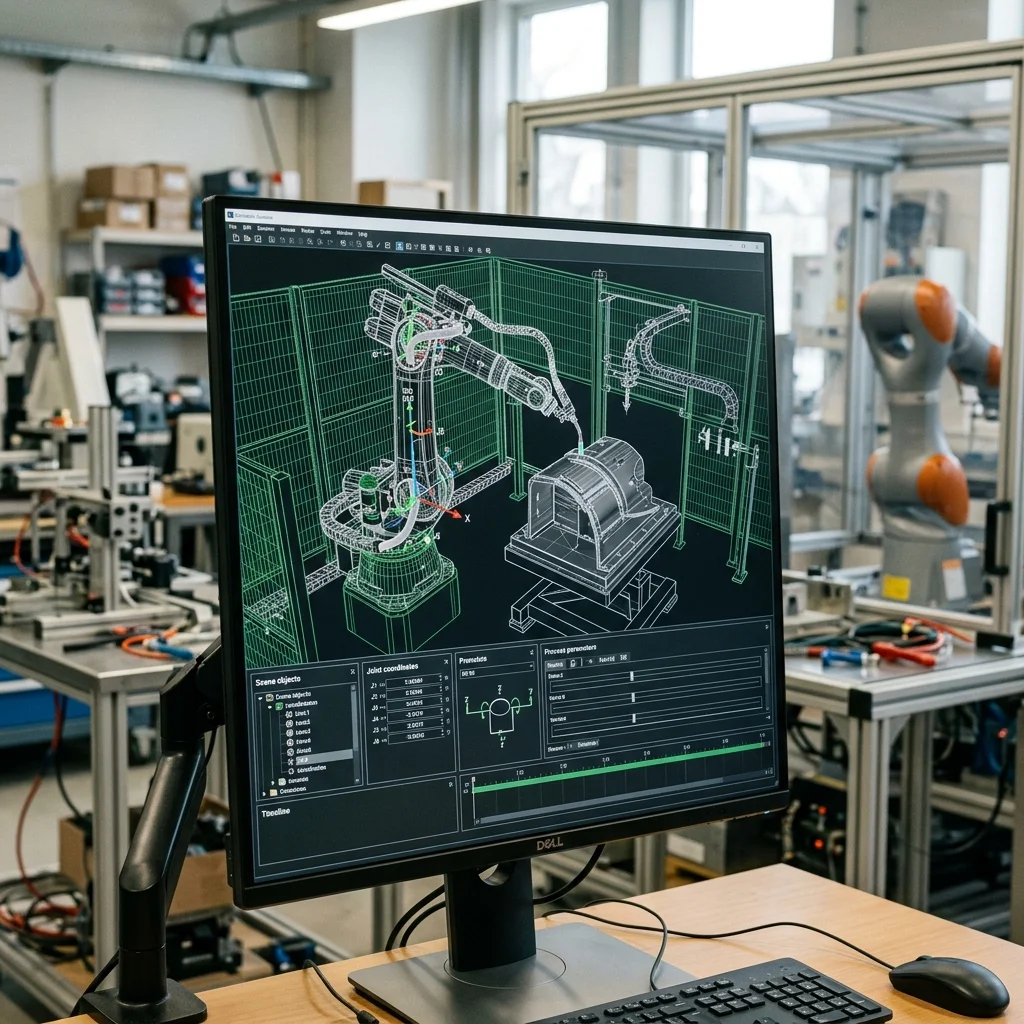
The third rule is to perform physical clearance checks. During simulation and virtual commissioning, engineers should model the dresspack's volume to verify it does not collide with the robot's own structure or the tool stand. After installation, the integration team must jog the physical robot slowly through its path, monitoring the dresspack for tension or compression.
Dresspack Inspection and Preventative Maintenance Checklist
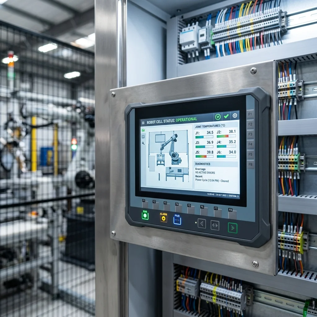
Even a well-designed dresspack is a wear item that requires regular inspection to prevent failures. Mechatronics maintenance teams should perform visual checks weekly. Inspect the outer corrugated conduit for cracks, flat spots, or signs of wear indicating contact with cell fixtures, replacing damaged conduits before internal cables are affected.
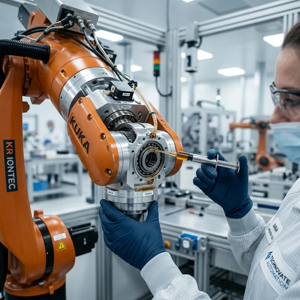
Second, verify the operation of the spring retraction system, checking that the slider moves smoothly and maintains tension on the conduit without binding. Third, inspect cable entry points and strain-relief clamps to ensure the cables are not sliding inside the conduit, which would cause tension to accumulate at the connectors. Finally, check all electrical and pneumatic connections for signs of loose fittings or air leaks.