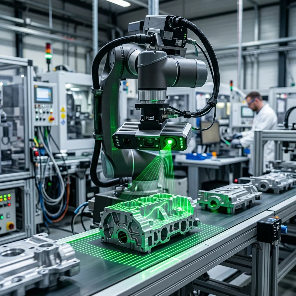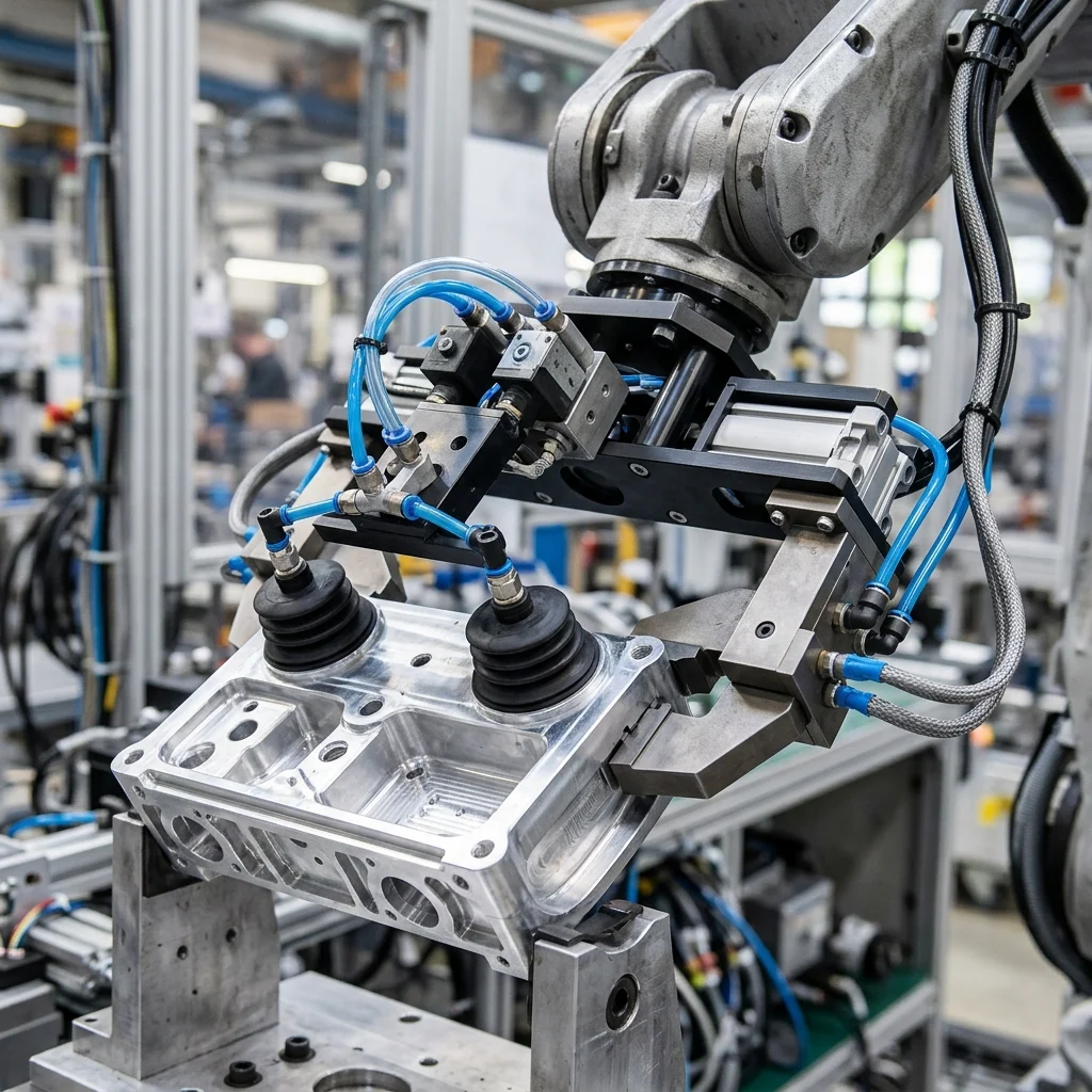
Optimizing robotic coating cells to achieve automotive-grade finish quality requires fine-tuning four core spray parameters: fluid flow rate, atomization air pressure, shaping air pressure, and electrostatic voltage. Coordinating these parameters with the robot's TCP speed and path overlap prevents defects like orange peel, runs, and sagging while maximizing paint transfer efficiency.
The Physics of Atomization and Spray Patterns in Robotic Painting
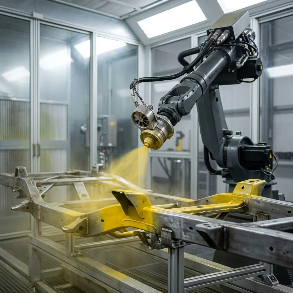
Robotic painting and coating cells are highly specialized environments where fluid dynamics and robotics kinematics intersect. Achieving a defect-free finish requires precise atomization—the process of breaking bulk liquid paint into a fine mist of microscopic droplets. Most industrial painting robots use rotary atomizers or air-atomizing spray guns mounted on explosion-proof wrist assemblies to apply paint uniformly.
A rotary atomizer uses a bell cup spinning at speeds up to 60,000 RPM. Centrifugal force pushes the paint to the edge of the cup, where it is sheared into fine droplets. Surrounding the cup are shaping air nozzles that project a stream of compressed air to control the width and direction of the spray pattern. Programmers must adjust the ratio of atomization speed to shaping air flow to balance paint distribution across the workpiece.
In contrast, air-atomizing spray guns use high-velocity compressed air streams to shear the paint stream emerging from the fluid nozzle. This approach is common for lower-viscosity fluids and complex, recessed geometries where the high-velocity air can project paint into tight cavities. Regardless of the applicator type, tuning the fluid properties and air parameters is essential to establish a reliable, repeatable process.
Tuning Core Spray Parameters: Flow Rates, Air Pressures, and Fan Widths
Tuning a robotic coating cell requires systematic adjustment of several core parameters. The fluid flow rate (measured in cubic centimeters per minute, or cc/min) determines the volume of paint delivered to the applicator. The flow rate must be scaled to match the robot's TCP speed. If the robot speeds up, the flow rate must increase proportionally to maintain a consistent wet film thickness.
Atomization air pressure controls the droplet size distribution. Higher pressure shears the paint into smaller droplets, creating a smoother finish. However, if the pressure is too high, the droplets become too small and evaporate or get carried away by air currents, reducing transfer efficiency. Shaping air pressure controls the fan width. Adjusting this parameter allows the robot to spray a wide pattern on flat surfaces and a narrow pattern on edges.
If these parameters are out of balance, finish defects will occur. For example, 'orange peel' (a textured finish resembling citrus skin) occurs when the atomization pressure is too low or the paint viscosity is too high, preventing the droplets from coalescing smoothly on the surface. Conversely, runs and sags occur when the fluid flow rate is too high or the robot's path speed is too slow, depositing excess paint.
Electrostatic Paint Application and Transfer Efficiency
To reduce paint consumption and VOC (Volatile Organic Compound) emissions, modern robotic cells employ electrostatic application technology. In an electrostatic system, a high-voltage charge (typically between 30 kV and 90 kV) is applied to the paint droplets as they emerge from the applicator. The workpiece is connected to electrical ground, creating an electrostatic field between the gun and the part.
Because opposite charges attract, the charged paint droplets are pulled toward the grounded part, significantly increasing transfer efficiency. While standard air spray systems have a transfer efficiency of 30% to 50% (meaning half the paint is wasted as overspray), electrostatic systems can achieve efficiencies exceeding 85%. This technology also exhibits a 'wrap-around' effect, where paint droplets curve around edges to coat the backside of tubes and brackets.
However, electrostatic painting introduces safety risks. The high-voltage system can generate sparks that ignite paint solvents if the applicator gets too close to the grounded part. Painting robots must integrate safety monitoring systems that detect current spikes and shut down the high-voltage supply in milliseconds. The distance between the applicator and the part must be simulated and controlled during path programming to prevent arcing.
Path Programming: Offsets, Speed Control, and Overlap
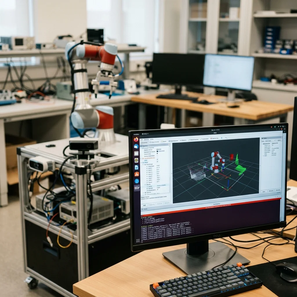
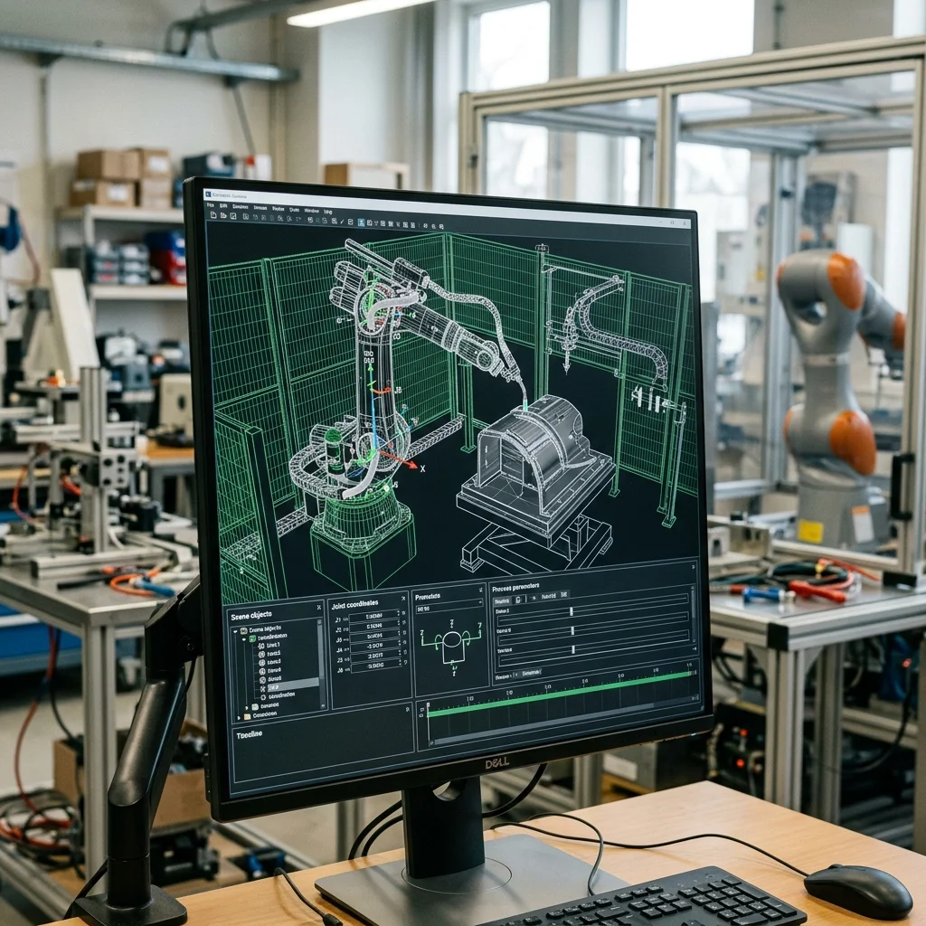
Robot path programming for painting relies on maintaining a consistent standoff distance (offset) and tool orientation. The spray gun must remain perpendicular to the surface of the part at all times. If the robot tilts the gun, the paint pattern becomes distorted, causing uneven film thickness. OLP software should be used to simulate the gun's orientation relative to the 3D part geometry.
The robot's path is typically programmed using a parallel grid pattern (raster scan). The distance between adjacent passes—the path pitch—must be calculated to provide a 50% overlap of the spray pattern. This overlap ensures that the thin edges of the spray fan blend together, creating a uniform coating layer. If the pitch is too wide, banding lines will appear; if it is too narrow, the paint will build up and sag.
Velocity control is also critical. Painting robots must run at a constant speed (usually between 300 mm/s and 800 mm/s) while the applicator is active. Modern controllers feature 'gun trigger' instructions that turn the spray on and off with millisecond precision, matching the robot's acceleration ramps. This ensures that the paint is applied only when the robot is moving at its target speed, preventing heavy deposits at path start and stop points.
Coating Process Commissioning and Optimization Checklist
Before executing production runs, the integration team must run through a commissioning checklist to optimize the cell. First, verify the grounding path of the part fixtures, as a poor ground will disable the electrostatic wrap-around effect and lower transfer efficiency. Second, calibrate the fluid delivery pumps to ensure the actual flow rate matches the controller's target output within 1%.
Third, test the safety interlocks on the electrostatic system, verifying that the high-voltage supply cuts out immediately if the applicator approaches a grounded object. Fourth, perform a wet-film thickness measurement on test parts using a comb gauge, adjusting the robot's speed and flow rate to meet specification limits. Finally, verify the exhaust airflow in the spray booth to ensure paint fumes are extracted safely without distorting the spray fan.