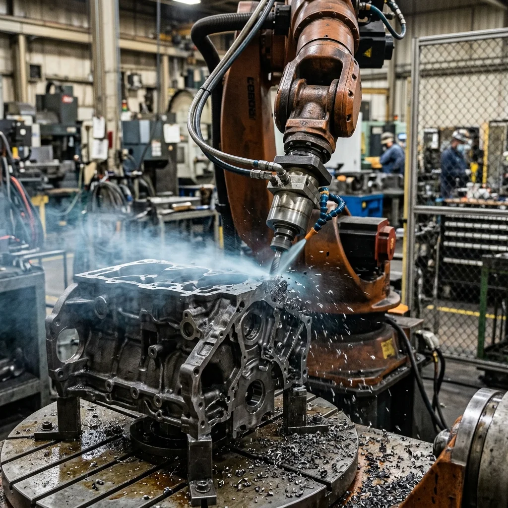
Robotic deburring automated cells require matching the compliance tool mechanical characteristics to the material being finished. Implementing pneumatic compliant spindles or active force control allows the deburring tool to follow the part's actual contours, compensating for casting tolerances and preventing defects like gouging or incomplete burr removal.
The Challenge of Varying Burr Geometries in Foundry Operations
Deburring is one of the most physically demanding and hazardous tasks in foundry and machining environments. Handheld grinding tools generate vibration, dust, and noise, leading to operator fatigue and repetitive strain injuries. Transitioning this process to robotic cells improves workplace safety and ensures consistent finish quality. However, deburring introduces significant automation challenges due to variations in burr size.
Unlike machining operations where the workpiece dimensions are predictable, castings and machined parts have varying burr sizes and locations. A flash line on a cast iron engine block can vary in thickness by several millimeters from batch to batch. If a robot follows a rigid, pre-programmed path, it will gouge the part where the burr is thin and leave excess material where the burr is thick.
To address this variability, deburring cells must be designed with compliance. Compliance allows the cutting tool to float mechanically or electronically, maintaining a constant contact force against the workpiece. This enables the robot to follow the physical contour of the part, compensating for dimensional variations and tool wear without gouging the base metal.
Selecting Deburring Spindles: Pneumatic vs. Electric
Selecting the correct spindle is the first step in deburring cell design. Spindles are categorized by their power source: pneumatic or electric. Pneumatic spindles are lightweight, simple, and can run at high rotational speeds (up to 40,000 RPM). They are suitable for deburring plastics, aluminum castings, and small steel components using rotary burs or mounted wheels.
Pneumatic spindles also offer natural compliance. By regulating the air pressure supplied to the spindle's internal turbine, engineers can control the torque and rotation speed. If the tool encounters a heavy burr, the spindle slows down, preventing tool breakage. However, pneumatic systems consume significant compressed air and lack precise speed feedback, which can lead to tool wear in hard metals.
Electric spindles use servo or brushless DC motors to provide precise speed control and torque feedback. They maintain a constant rotational speed under load, which is critical for achieving consistent finishes in tough materials like cast iron or titanium. Electric spindles can also export torque data to the robot controller, allowing the system to monitor tool wear and adjust path feedrates dynamically.
Mechanical Compliance and Tool Float Systems
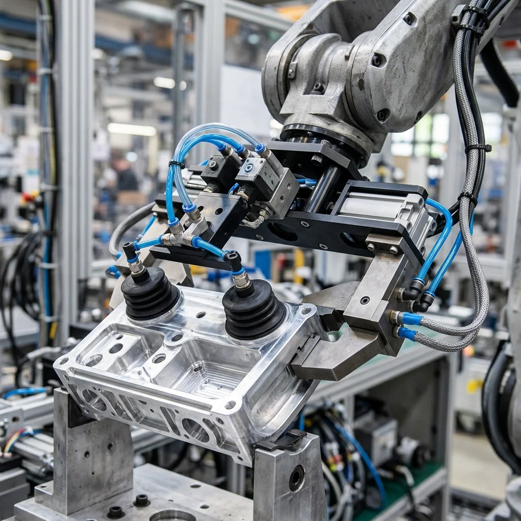
Mechanical compliance tools (often called float holders) are designed to absorb part misalignments and tolerances. A typical compliant tool features a spring-loaded or pneumatically pressurized joint that allows the spindle to deflect in the radial (side-to-side) or axial (push-in) direction. The compliance force is regulated by adjusting spring tension or air pressure.
Radial compliance tools are widely used for deburring edges and flash lines. The tool is programmed with a path offset that pushes the spindle slightly against the part. The compliance mechanism allows the tool to deflect, maintaining contact even if the edge shifts by several millimeters. This float prevents gouging and ensures that all burrs are removed uniformly.
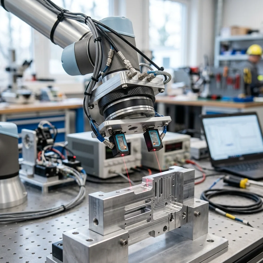
Axial compliance tools are suited for chamfering and finishing flat surfaces. The spindle can slide along its axis, absorbing height variations. For complex parts, active force control systems can replace mechanical compliance. Active systems use force-torque sensors at the flange to measure contact forces, adjusting the robot's trajectory in real time to maintain a target force, though they require more advanced programming.
Programming Deburring Paths: Feedrates and Tool Angles
Programming deburring paths requires careful adjustment of feedrates and tool angles. The feedrate (measured in millimeters per second) must be matched to the material and the tool capacity. If the robot moves too fast, the tool will bounce over the burrs, leaving defects; if it moves too slow, the tool will overheat, hardening the work surface and accelerating tool wear.
The orientation of the tool relative to the part edge is another critical parameter. Rotary burs should be tilted slightly (typically 5 to 15 degrees) in the direction of travel to prevent chatter. Chatter is a high-frequency vibration that occurs when the cutting teeth grab the metal unevenly, creating a wavy finish. Tilting the spindle distributes the cutting forces and stabilizes the tool.
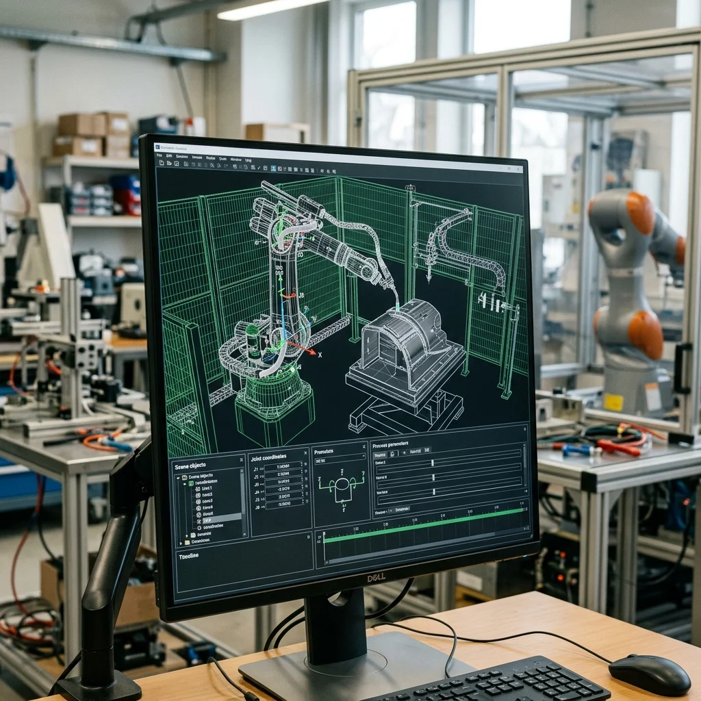
Programmers should utilize offline programming (OLP) tools to generate paths from CAD data. OLP software can automatically calculate the normal vector for complex 3D curves, ensuring the tool maintains the correct angle. After generating the virtual path, calibration targets must be used to align the virtual coordinate system with the physical cell fixtures, ensuring absolute path accuracy.
Deburring Cell Commissioning and Tuning Checklist
Before starting automated deburring, the integration team must verify the mechanical and control parameters. First, inspect the spindle bearings and check for runout to ensure the tool rotates without vibration. Second, regulate the compliance air pressure, setting it to a level that removes burrs without cutting into the part's base metal.
Third, test the tool wear monitoring logic, verifying that the system halts production or alerts the operator if spindle torque exceeds safety thresholds. Fourth, jog the robot through its path at low speed to confirm that the compliance mechanism does not bottom out during transitions. Finally, check that the dust extraction system is functional to collect metal particles safely.